Do you have a question about the Snapper 280915BE and is the answer not in the manual?
Details on installing the steering shaft, bushing, washer, and cotter pin.
Instructions for attaching tie rods to the steering shaft for narrow frames.
Instructions for attaching tie rods to the steering shaft for wide frames.
Procedures for checking blade torque, alignment, and straightness.
Guidance on performing lubrication and checking fluid levels.
Steps to install the fuel tank and connect the fuel line.
Procedure for safely removing the battery from the battery box.
Steps for activating, filling, and charging the electric start battery.
Guidance on installing the battery, connecting cables, and securing.
Final step to connect the electrical circuit at the rear of the engine.
Instructions for performing engine service, oil, and fuel checks.
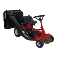
This document provides comprehensive setup instructions and a pre-sale checklist for the SNAPPER Series 15 Rear Engine Riders, covering various models including 250815B, 250815BE, 280915BE, 300915BE, 301215BE, 331415BVE, 331415KVE, 421615BVE, and 421615TVE. The manual is designed for dealers to ensure proper assembly and preparation of the unit before delivery to the customer.
The SNAPPER Series 15 Rear Engine Riders are designed for lawn maintenance, specifically mowing. These riders are shipped with certain components detached to minimize their profile during shipment, including steering components, the seat, and the fuel tank. The setup process involves assembling these detached parts, performing essential checks, and preparing the unit for operation.
The core function of the setup is to ensure all mechanical and electrical systems are correctly installed and functioning safely. This includes the steering system, which allows the operator to control the direction of the mower. The mowing deck, with its cutting blade, is central to the device's purpose, and its proper installation and adjustment are critical for effective grass cutting. The fuel system ensures the engine receives the necessary fuel, while the electrical circuit is vital for starting the engine and powering other electrical components. The operator's seat provides comfort and includes a safety switch to prevent operation without an operator. Finally, the chute deflector directs grass clippings away from the operator and surrounding areas.
The setup instructions highlight several usage features that contribute to the overall operation and safety of the SNAPPER Rear Engine Riders.
Steering System: The steering shaft is installed first, followed by the tie rods. For narrow front frames (28" and smaller decks), tie rods are secured with flat washers and cotter pins. For wider front frames (30" and larger decks), tie rods are secured with lock washers and hex nuts, tightened securely. The steering wheel is then slid onto the steering shaft. The offset of the steering wheel can be oriented towards the operator's seat for normal operation or towards the front for more operator room. A roll pin secures the steering wheel to the shaft. This modular design allows for flexibility in steering configuration based on operator preference.
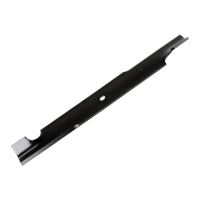
Mowing Deck: The cutting blade's mounting bolt torque is specified (35 to 55 ft. lbs.), and for 28" and 33" decks, air lift mounting bolts have a torque specification of 135 to 155 in. lbs. The blade's straightness is also checked, ensuring an even cut. These checks are crucial for optimal cutting performance and safety.
Fuel System: The fuel tank is designed to snap into a bracket behind the seat. The fuel line connects to a hose barb on the fuel tank, secured with a hose clamp. A fuel filter, pre-installed by the engine manufacturer, ensures clean fuel delivery to the engine. This straightforward fuel system design simplifies refueling and maintenance.
Operator's Seat: For 8 and 9HP models, the seat lays onto the seat pan, and the seat switch wiring harness connects to male tabs under the seat. The seat is then positioned on the seat bracket and secured with hex head flange patch lock screws. Spacers and adjusting knobs allow the operator to adjust the seat's position for comfort and secure it in place. For 12, 14, and 16HP models, a hinged seat plate is folded forward before following similar steps. This adjustable seat design enhances operator comfort and safety.
Battery (Electric Start Models): The battery for electric start models is shipped dry and requires activation with electrolyte and charging. The battery cover is designed for easy removal and reinstallation using ratchet fasteners. Battery cables are secured to terminals with screws and lock-nuts, and a positive terminal insulator is placed over the positive terminal and cable. This ensures a secure and safe electrical connection for starting the engine.
Chute Deflector: The chute deflector is shipped in an "UP" position and is secured to the deck with carriage bolts, flat washers, and wing-nuts. This feature is essential for directing grass clippings safely during operation.
Electrical Circuit: The electrical connection at the engine is shipped disconnected for safety and is the last step in preparation. This prevents accidental activation of the electrical system during setup.
The setup instructions also touch upon several maintenance features that are integral to the long-term care and performance of the SNAPPER Rear Engine Riders.
Lubrication: The manual emphasizes performing normal lubrication of the Rear Engine Rider and checking differential and chain case for proper lubricant levels, referring to the Operator's Manual for detailed instructions. Regular lubrication is critical for reducing wear and extending the lifespan of moving parts.
Mowing Deck Checks: Beyond initial setup, the checklist includes ongoing maintenance items for the mowing deck, such as checking blade retaining bolt torque, air lift bolt torque, blade alignment, and blade straightness. These checks ensure consistent cutting quality and prevent damage to the blade or deck.
Battery Maintenance: For electric start models, the battery requires activation with electrolyte and charging. The instructions detail how to remove cell caps, fill with electrolyte, and slow charge the battery. Regular checks of electrolyte levels and proper charging are essential for battery longevity and reliable starting. The warning about handling electrolyte (acid) and the need for eye protection highlights the importance of safe maintenance practices.
Engine Service: The instructions direct the dealer to perform engine service, including oil and fuel, according to the engine manufacturer's recommendations. This ensures the engine operates efficiently and reliably.
Pre-Sale Checklist: The comprehensive pre-sale checklist serves as a maintenance and quality assurance tool. It covers checks for steering, tie rods, lubrication, seat installation, fuel system, grass deflector, battery, tire pressure, cutting blade, deck settings (height, side-to-side, front-to-rear), blade lever, belt tension, engine oil, differential, chain case, yoke lift, and fuel system for leaks. This checklist ensures that all components are in optimal condition and properly adjusted before the rider is delivered to the customer, minimizing potential issues and maximizing the device's operational life.
Demonstration & Instruction: The final step involves personally handing the Operator's Manual and Mower Safety Booklet to the owner, instructing them to read and follow instructions, demonstrating proper operation, explaining air cleaner service and engine oil check procedures, and assisting with product registration. This educational aspect empowers the owner to perform routine maintenance and operate the device safely and effectively.
| Part Number | 280915BE |
|---|---|
| Type | Blade |
| Material | Steel |
| Length | 21 inches |
| Width | 2.25 inches |
| Compatible Models | Snapper |