EasyManua.ls Logo

Snapper PRO - User Manual

Snapper PRO
8 pages
Print Icon
To Next Page IconTo Next Page
Loading...
1
SET-UP INSTRUCTION & PRE-OPERATION CHECKLIST
SNAPPER PRO 21" STEEL DECK COMMERCIAL WALK BEHIND MOWERS
INTRODUCTION: The SNAPPER PRO Walk Behind Mowers are shipped almost fully assembled and require
minimal set-up. Complete each of the following steps carefully. Review and complete each item as instructed
on the Pre-Operation checklist.
WARNING – DO NOT ATTEMPT TO START OR
OPERATE THIS UNIT UNTIL ALL ASSEMBLY
STEPS HAVE BEEN COMPLETED. SERIOUS
INJURY OR EQUIPMENT DAMAGE MAY RESULT.
HANDLE ASSEMBLY
STEP 1: Remove mower from shipping carton. These
mowers are manufactured with (4) 5/16-18 hex head
cap screws, and (4) 5/16 bolt retainers that secure the
upper, middle handles and lower handle brackets
together for packaging purposes. This hardware will
have to be removed and discarded. See Figure 1.
REMOVE EXISTING HARDWARE
FIGURE 1
STEP 2: New hardware can be found in hardware bag.
Attach middle handle to lower handle brackets using
5/16-18 x 1-1/2” curved head bolts, installed from the
inside of handles as shown, and secure with 5/16
internal tooth lock washers and hex nuts. Do not tighten
at this time. See Figure 2.
STEP 3: Attach the upper handle assembly to the middle
handle using 5/16-18 x 1-1/2” curved head bolts,
installed from the inside of handles as shown, and
secure with 5/16 internal tooth lock washers and hex
nuts. Do Not tighten at this time. See Figure 3.
FIGURE 2
FIGURE 3
FIGURE 4
INSTRUCTION No. 7103223 (Rev. ‘-’, 3/18/2009)
UPPER
HANDLE
MIDDLE
HANDLE
5/16 BOLT
RETAINER
5/16 BOLT
RETAINER
5/16 HEX HEAD CAP
SCREWS
5/16 HEX
HEAD CAP
SCREWS
MIDDLE
HANDLE
5/16 BOLT
RETAINER
LOWER
HANDLES
MIDDLE
HANDLE
LOWER
HANDLE
(Left Side)
5/16 X 1-1/2”
CURVED
HEAD BOLT
5/16 HEX
NUTS
5/16 LOCK
WASHERS
UPPER
HANDLE
MIDDLE
HANDLE
INTERNAL
TOOTH LOCK
WASHER
5/16 X 1-1/2”
CURVED
HEAD BOLTS
HEX NUT
LOWER HANDLE
BRACKET
LOOSEN
THREE NUTS
Not for
Reproduction
Question and Answer IconNeed help?

Do you have a question about the Snapper PRO and is the answer not in the manual?

Summary

Handle Assembly

Connect Middle to Lower Handle

Attach middle handle to lower handle brackets with bolts and washers.

Connect Upper to Middle Handle

Attach upper handle assembly to middle handle using bolts and washers.

Install Handle Braces

Secure handle braces between lower handles and drive disc bracket.

Install Operator Console and Levers

Mount operator console and attach speed control levers.

Drive Assembly

Connect Ground Speed Control Rod

Install the ground speed control rod into the pivot arm ball joint.

Discharge Assembly

Install Grass Bag and Adapter

Secure grass bag adapter and grass bag to the mower deck.

Pre-Operation Checklist

Overview

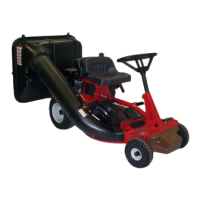
This document is a set-up instruction and pre-operation checklist for the Snapper Pro 21" Steel Deck Commercial Walk Behind Mowers. It provides detailed steps for assembling the mower and a checklist to ensure all necessary adjustments and checks are completed before operation.

Function Description:

The Snapper Pro 21" Steel Deck Commercial Walk Behind Mower is designed for commercial use, offering robust construction and features suitable for demanding lawn care tasks. The manual guides users through the initial assembly and setup process, which includes attaching the handles, installing the operator console, setting up the drive assembly, and preparing the discharge system. The pre-operation checklist serves as a final verification tool to ensure the mower is safe and ready for use, covering aspects from hardware security to fluid levels and operational tests.

Important Technical Specifications (derived from the manual):

  • Deck Material: Steel
  • Cutting Width: 21 inches
  • Hardware:
    • Handle Assembly: 5/16-18 hex head cap screws, 5/16 bolt retainers, 5/16-18 x 1-1/2" curved head bolts, 5/16 internal tooth lock washers, 5/16 hex nuts.
    • Operator Console: Four 1/4-20 x 1/2" torx screws.
    • Ground Speed Handle: One 8-32 x 1/2" round head machine screw and hex nut.
    • Handle Braces: 5/16-18 x 3/4" hex washer head bolt and flange nut.
    • Ground Speed Control Rod: 1/4-28 jam nut.
    • Blade Retaining Bolt(s) Torque: 40 ft. lbs. (recommended).
  • Clutch Cable Clearance: 1/16" - 1/8" between spring hook and cable loop when wheel drive control handle is released.
  • Engine Type: 4-cycle engines (oil level to full mark) or 2-cycle engines (oil mixed with fuel in specified ratio).
  • Differential: Grease checked and added if needed.

Usage Features:

  • Adjustable Handle Height: The handle height can be adjusted by loosening bolts on the lower handle brackets, moving the handles up or down to the desired height, and then tightening all bolts and nuts. This allows operators to customize the mower for ergonomic comfort.
  • Brake Control: A squeeze brake control is integrated into the upper handle. Squeezing it against the upper handle allows the engine recoil to be pulled and hooked into the rope guide.
  • Operator Console: The console houses the engine speed handle and ground speed lever handle, providing convenient access to operational controls. The engine speed handle is firmly pressed onto the right lever, and the ground speed handle is secured to the left lever with a screw and nut.
  • Drive Assembly: The drive system includes a driven disc, drive disc spring, and transfer rod. Adjustments to the driven disc position are made to ensure proper operation. The ground speed control lever, when fully forward, engages the drive, and its threaded rod connects to a ball joint on the speed control pivot arm.
  • Discharge Options: The mower supports multiple discharge configurations:
    • Grass Bag: The grass bag adapter is installed on the side and top of the deck, and the grass bag itself is assembled with a top wire and slider, then hooked onto the middle handle.
    • Discharge Deflector (Optional): If discharging is desired, the grass bag and adapter can be removed, and a discharge deflector installed in their place, secured with the same hardware.
    • Recycling Plug (Optional): For mulching, a recycling plug can be inserted completely and securely into the adapter after removing the grass bag. The grass bag can then be reinstalled as a safeguard.
    • Recycling Cover (Optional): A recycling cover can be installed on the side and top of the deck, with its slot positioned underneath a nut, to facilitate recycling.
  • Recoil Start: The recoil rope is routed around a rope guide pulley on the bag adapter. Pulling the blade control up against the upper handle frees up recoil slack, allowing for easier starting.
  • Commercial Use: The mower is explicitly designed for commercial applications, implying durability and performance suitable for professional landscapers.

Maintenance Features (derived from the checklist and instructions):

  • Pre-Operation Checklist: A comprehensive checklist ensures all components are properly installed, adjusted, and secured before initial use. This includes verifying hardware tightness, fluid levels, and operational tests.
  • Foam Shipping Block Removal: A foam shipping block must be removed from the cutting blade before starting the engine. This prevents damage and ensures proper blade function.
  • Fluid Checks:
    • Engine Oil: For 4-cycle engines, engine oil must be added to the full mark. For 2-cycle engines, oil must be mixed with fuel in the specified ratio.
    • Differential Grease: Differential grease should be checked and added if needed.
  • Blade Retaining Bolt(s) Check: The blade retaining bolt(s) must be checked and tightened securely to 40 ft. lbs.
  • Clutch Cable Adjustment: While factory-set, instructions are provided for reference to adjust the clutch cable clearance (1/16" - 1/8") to ensure proper drive system engagement and disengagement.
  • Drive Disc Adjustment: The drive disc position needs to be adjusted to ensure correct operation of the drive system.
  • CPSC Compliance Test: The blade control's ability to stop the engine when released is a critical safety check.
  • Warning on Tipping: Users are warned NOT to tip the machine with the carburetor or spark plug down, as oil from the crankcase can saturate the air filter, making the engine hard or impossible to start. If contamination occurs, the air filter must be replaced.
  • Grass Catcher/Guard Inspection: A warning emphasizes that the mower should NOT be operated without the entire grass catcher or guard in place. These components are subject to deterioration and must be inspected frequently and replaced if worn or damaged.
  • Documentation Retention: The pre-operation checklist form is to be retained for future reference regarding warranty, proof of purchase, traceability for product recall, or service.

Snapper PRO Specifications

General IconGeneral
BrandSnapper
ModelPRO
CategoryLawn Mower Accessories
LanguageEnglish

Related product manuals