4
STEP 2:
IMPORTANT: Clutch cable adjustments are made to the
machine at the factory. The following adjustments are
provided for reference only. Complete all items on the
Pre-Operation Checklist as instructed.
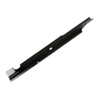
Check the clearance between the clutch cable and
clutch spring. NOTE: Clearance between spring and
cable is very important. Excessive clearance will cause
drive system NOT to operate when wheel drive control
handle is depressed. No clearance at all will cause
mower to continue to propel itself when wheel drive
control handle is released to stop mower movement.
Slide vinyl spring cover (located at the end of clutch
cable) up clutch cable to gain access to the end of
spring and cable loop. With wheel drive control handle
released, clearance between spring hook and cable
loop should be 1/16” to 1/8”. If clearance is more or less
than specified, unhook spring from clutch cable eye,
then adjust by turning inner spring in an opposite
direction than the outer spring. Rehook spring to clutch
cable eye. Slide vinyl cover over the spring when
correct clearance is reached. See Figure 13.
FIGURE 13
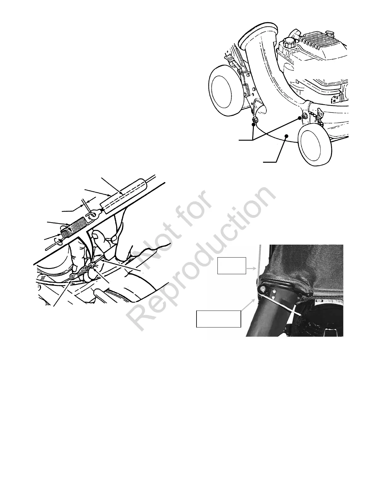
DISCHARGE ASSEMBLY
NOTE: Discharge assemblies vary by model. Some
assembly steps shown may not apply to your model.
GRASS BAG
STEP 1: Install the grass bag adapter and secure to the
side and top of the deck with the two nuts provided with
the machine. Slot in front edge of adapter must be under
nut located on top of deck. See Figure 14.
FIGURE 14
STEP 2: Route recoil rope around rope guide pulley on
top of bag adapter. See Figure 15. NOTE: Pulling
blade control up against upper handle will free up recoil
slack.
FIGURE 15
SPRINGS
INNER
SPRING
OUTER
SPRING
1/16” - 1/8”
CLEARANCE
VINYL SPRING
COVER
CLUTCH CABLE
CABLE
CLUTCH
CABLE EYE
SECURE ADAPTER
TO DECK WITH NUTS
SECURE
WITH NUTS
ADAPTER
ROPE GUIDE
PULLEY
RECOIL
ROPE