The document is a Safety Instructions & Operator's Manual for SNAPPER 21" HI-VAC --SERIES 7 walk-behind mowers. It covers various models including 21357B, M21357B, D21357B, P21357B, PM21357B, PD21357B, 21407T-2, P21407T-2, 21507B, P21507B, and P21507BE. The manual emphasizes safety, operation, and maintenance procedures for these lawn mowers.
Function Description
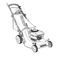
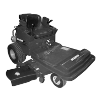
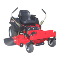
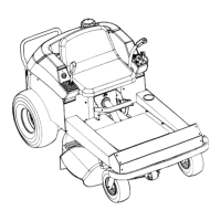
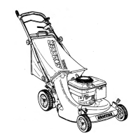
The SNAPPER 21" HI-VAC --SERIES 7 mowers are designed for residential and commercial lawn care. They are walk-behind models, available in both push and self-propelled configurations. These mowers are versatile and can perform several lawn care duties with the appropriate attachments:
- Mulching: With a MULCHER kit, the mower cuts and chops grass into small, nutritious mulch particles, blowing them directly onto the lawn. The MULCHER BLADE is suitable for both mulching and side discharging operations.
- Bagging: When equipped with a GRASS BAG kit, the mower collects clippings into a grass bag. This is achieved by using a BAG ADAPTOR and a standard cutting blade for optimum bagging.
- Side Discharge: Models with a "D" prefix are side discharge models, broadcasting clippings to the side. Grass bag equipped models can be converted to side discharge units with a SIDE CHUTE KIT.
- Thatching: The THATCHERIZER KIT (recommended for self-propelled models) helps prevent harmful thatch accumulation by dethatching the lawn periodically. The dislodged thatch can then be vacuumed with a grass bag.
- Vacuuming/Shredding: The SNAPPERIZER KIT converts the mower into an outdoor vacuum "shredder" for grass clippings and leaves, which can then be broadcast or collected in a grass bag.
The engine (and blade) is stopped by releasing the BLADE CONTROL or pulling the ENGINE CONTROL lever to the STOP position. On self-propelled models, releasing the WHEEL DRIVE control stops the forward movement.
Important Technical Specifications
- Model Designations:
- "P" prefix: Self-propelled models.
- "M" prefix: Mulcher models.
- "D" prefix: Side discharge models.
- "B" suffix: Powered by a Briggs & Stratton engine.
- "E" suffix: Electric Start models.
- "T" suffix: Tecumseh powered.
- "-2" designation: 2-cycle engine.
- Cutting Width: 21 inches.
- Blade Retention Torque: 30 FOOT POUNDS.
- Blade Sharpening Angle: 22 to 28 degrees, with the cutting surface extending inward about 3-1/2" from the tip.
- Clutch Linkage Clearance (Self-Propelled): 1/16" to 1/8" clearance between the INSIDE of the spring hook and the INSIDE of the clutch cable "eye".
- Driven Disc Adjustment (Self-Propelled): The center of the driven disc should be 1/8" to 1/4" from the edge of the drive disc in the highest speed setting.
- Battery Charging: A plug-in battery charger (available from Snapper Dealer) operates on 120V/60 Hz household current. Weak batteries require 48 hours of charging, fully discharged batteries require 72 hours.
Usage Features
- Engine Control Lever (10): Used to set engine speed (FAST for tall/thick grass, SLOW for shorter/less dense grass) and for CHOKE/START/STOP positions.
- Blade Control (7): Must be held against the UPPER HANDLE (18) for the engine to start and to engage the blade. Releasing it stops the engine and blade.
- Wheel Drive Control (19): On self-propelled models, grasping this control against the UPPER HANDLE (18) engages the clutch for forward movement. Releasing it stops forward movement.
- Ground Speed Control (12): Allows adjustment of forward movement speed on self-propelled models.
- Adjusting Latches (1): Four latches for setting cutting height, ranging from notch 1 (lowest, 1" height) to notch 5 (highest, 3" height). It's recommended not to cut more than 1/3 of the grass height at once.
- Rope Start Handle (16): For manual engine starting.
- Key/Ignition Switch (13): For electric start models, with RUN & START positions. The engine cannot be stopped via this switch.
- Fuel Shut-Off Valve (17): If equipped, must be open for engine operation.
- Primer Button: If equipped, used to prime a cold engine.
- Handle Height Adjustment: Locknuts (A) on the handle (14) can be loosened to adjust the handle height.
- Handle Storage: Handles on push models can be tilted forward after loosening LOWER KNOBS (20). On self-propelled models, the transfer rod clip must also be disconnected.
Maintenance Features
- Pre-Start Checks:
- Inspect guards, grass bag, bag adaptor, deck cover, or side discharge chute for proper position and tightness. The interlock spring must be engaged for the engine to start.
- Clean cooling air intake screen on the engine.
- Check oil level in 4-cycle engines (dipstick 15) to the "FULL" mark.
- Check fuel level in tank; use correct fuel-to-oil ratio for 2-cycle engines.
- Ensure traction drive clutch control is disengaged before starting.
- Lubrication Schedule:
- Engine: Change oil every 25 hours; check oil level before each use.
- Transmission (self-propelled models): Check grease level every 25 hours. Add Snapper "OO" grease (Part No. 1-1050) if not visible on the INPUT GEAR.
- Moving Parts: Occasionally oil points of contact (e.g., ADJUSTING LATCHES, GROUND SPEED CONTROL, WHEEL DRIVE CONTROL).
- Cutting Blade Service:
- Inspect blade frequently for tightness and condition. Replace if chipped, bent, out of balance, or has a notch worn in the tip (wear limit shown in FIG. 9-B). Never operate with a blade worn to the extent shown in FIG. 9-C (dangerous).
- Sharpen dull blades at 22-28 degrees. Re-balance as needed.
- Reinstall blade with components in the proper sequence, ensuring the flange fits over the edge of the blade drive hub.
- Driven Disc Service (Self-Propelled):
- Check for grease on drive disc, broken/disconnected DRIVE SPRING, worn driven disc rubber ring, driven disc out of adjustment, or worn belts if the mower doesn't pull properly.
- Adjust driven disc position (1/8" to 1/4" from drive disc edge) by loosening connector hex nut (A-1).
- Replace worn driven disc rubber ring (B-1) by removing machine screws (G) and plate.
- Bearing replacement involves removing the snap ring (H) and retaining screws (I) to replace the bearing (J).
- Belt Service (Self-Propelled):
- Replace worn engine belts (Poly-V-Belt) if slippage occurs. This involves disconnecting the spark plug wire, emptying the fuel tank, unhooking the idler arm spring, removing the driven disc assembly, cutting blade, and hub.
- Reinstall the belt around the engine drive pulley and driven pulley, ensuring the idler arm is against the engine belt when the spring is reinstalled.
- For Poly-V-Belt replacement, the driven disc assembly must be removed first. The belt should be installed over the hex-shaft, idler pulley, and transmission pulley, ensuring it sits in each pulley's groove. The lower span of the Poly-V-Belt should be ABOVE the belt guide.
- Storage Procedure:
- Disconnect the spark plug wire.
- Tape all openings to prevent water entry during washing.
- Clean the underside of the deck thoroughly, scrape off grass accumulation, and wash with a hose. Clean all external surfaces.
- Lubricate exposed metal with a light coating of oil.
- Empty and wash the grass bag (if equipped), allowing it to dry.
- Store the mower in a dry, weather-protected area.
- Yearly Inspection: Have the mower inspected and serviced annually by an authorized Snapper dealer to ensure reliability and safety.
- Replacement Parts: Use only genuine Snapper replacement parts to assure adequate protection against injury and maintain warranty.