Section 4 - ADJUSTMENT & REPAIR
WARNING
DO NOT attempt any adjustments, maintenance or
service with the engine or blade running. STOP blade.
STOP engine. Set brake. Remove key. Remove spark
plug wire from spark plug and secure wire away from
spark plug. Engine and components can be extremely
hot. Avoid burns by allowing engine and components
sufficient time to cool.
4.2.9. 38" DECK LEVEL ADJUSTMENT
(FRONT TO REAR)
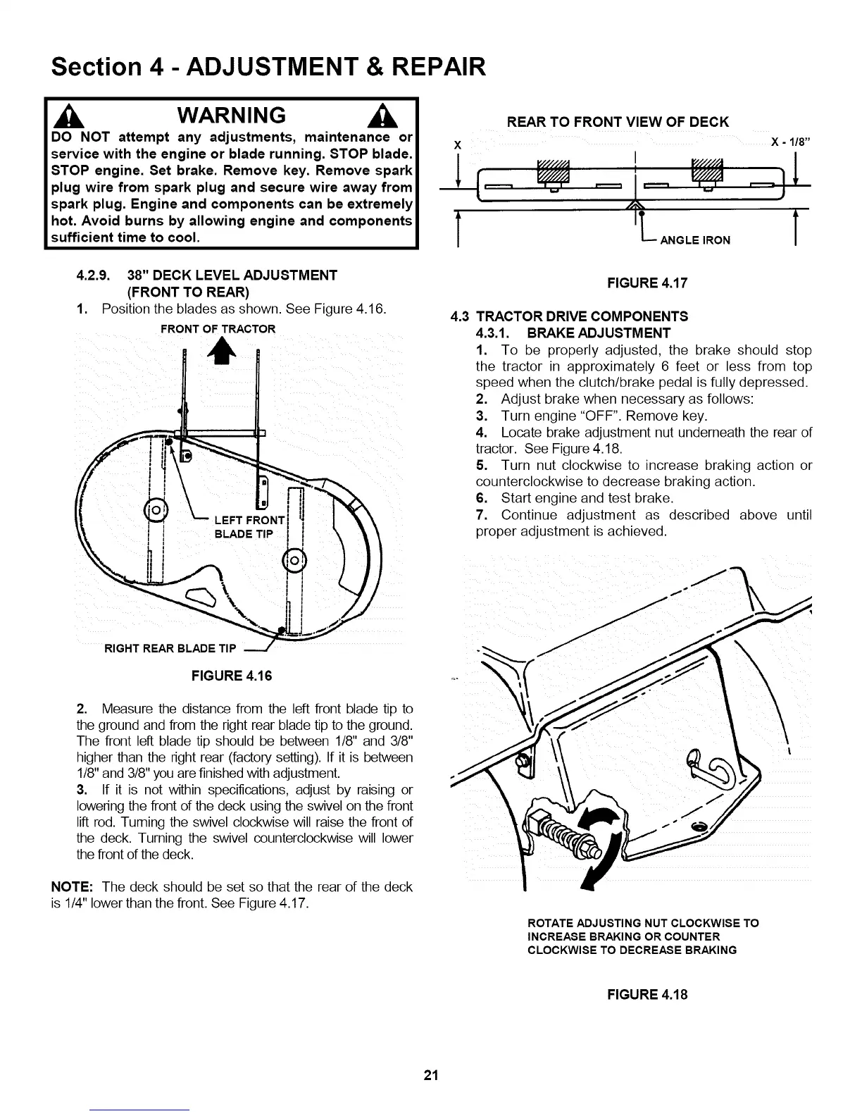
1. Position the blades as shown. See Figure 4.16.
FRONT OF TRACTOR
11,
FIGURE 4.16
2. Measure the distance from the left front blade tip to
the ground and from the right rear blade tip to the ground.
The front left blade tip should be between 1/8" and 3/8"
higher than the right rear (factory setting). If it is between
1/8" and 3/8" you are finished with adjustment.
3. If it is not within specifications, adjust by raising or
lowering the front of the deck using the swivel on the front
lift rod. Turning the swivel clockwise will raise the front of
the deck. Turning the swivel counterclockwise will lower
the front of the deck.
NOTE: The deck should be set so that the rear of the deck
is 1/4" lower than the front. See Figure 4.17.
X
1
4.3
REAR TO FRONT VIEW OF DECK
I
X - 1/8"
L ANGLE IRON 1
FIGURE 4.17
TRACTOR DRIVE COMPONENTS
4.3.1. BRAKE ADJUSTMENT
1. To be properly adjusted, the brake should stop
the tractor in approximately 6 feet or less from top
speed when the clutch/brake pedal is fully depressed
2. Adjust brake when necessary as follows:
3. Turn engine "OFF" Remove key.
4. Locate brake adjustment nut underneath the rear of
tractor. See Figure 4.18.
5. Turn nut clockwise to ncrease braking action or
counterclockwise to decrease braking action.
6. Start engine and test brake.
7. Continue adjustment as described above until
proper adjustment is achieved.
ROTATE ADJUSTING NUT CLOCKWISE TO
INCREASE BRAKING OR COUNTER
CLOCKWISE TO DECREASE BRAKING
FIGURE 4.18
21