39
6 3/8”
(16,2 cm)
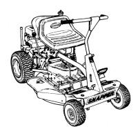
Figure 51. Hydraulic Drive Belt Replacement
A. Pump Drive Belt
B. Crankshaft Pulley
C. Transaxle Pulley
D. Idler Pulley
E. Idler Arm
F. Spring
G. Spring Anchor Eyebolt
B
D
A
C
F
G
E
C
Hydraulic Pump Drive Belt Replacement
1. Park the tractor on a smooth, level surface such as a
concrete floor. Disengage the PTO, engage the parking
brake, turn off the engine, and remove the ignition key.
2. Remove the PTO drive belt (see MOWER BELT
REPLACEMENT for removal instructions).
3. Remove the hardware that secures the clutch anchor
pad to the PTO clutch.
4. Loosen the nut on the spring anchor eyebolt (G, Figure
51) to release the majority of the belt tension. Use
caution and remove the nut to completely release the
tension.
5. Remove the old belt and replace it with the new one.
Make sure the V-side of the belt runs in the grooves of
the crankshaft pulley and transaxle pulleys (B & C).
6. Reinstall the spring anchor eyebolt (G) into the anchor
tab and loosely fasten the nut. Adjust the anchor
eyebolt until a measurement of 6-3/8” (16,2 cm) is
achieved from spring body. Tighten nut.
7. Reinstall the clutch anchor pad to the PTO clutch and
secure with the hardware previously removed.
8. Reinstall the PTO drive belt.
WARNING
STORED ENERGY DEVICE: Improper release
of the belt tension spring can result in personal
injury. Use extreme caution when removing
this spring.
Regular Maintenance