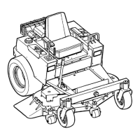
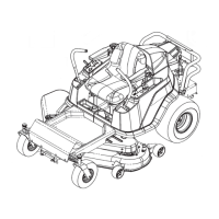
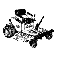
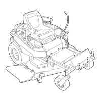
Removal (54" Mower Decks)
1. Disengage the PTO, engage the parking brake,
turn off the ignition, remove the key, andwait for all
moving parts to stop.
2. Remove the cutting height pin and lower the
attachment lift to its lowest position.
3. Remove the mower deck guards.
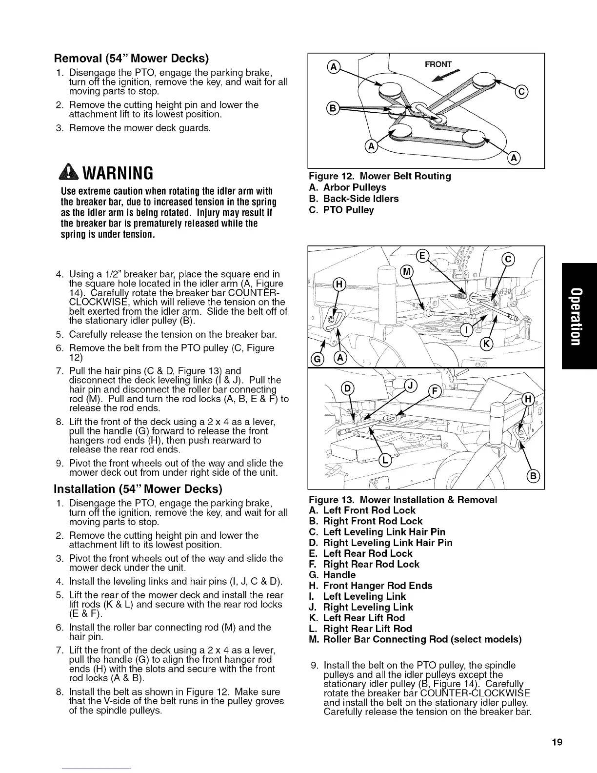
FRONT
WARNING
Useextreme cautionwhen rotatingthe idler armwith
the breakerbar, dueto increasedtension inthe spring
as the idler arm isbeing rotated. Injury may resultif
the breakerbar is prematurelyreleasedwhile the
springis undertension.
Figure 12. Mower Belt Routing
A. Arbor Pulleys
B. Back-Side Idlers
C. PTO Pulley
4. Using a 1/2" breaker bar, place the square end in
the square hole located in the idler arm (A, Figure
14). Carefully rotate the breaker bar COUNTER-
CLOCKWISE, which will relieve the tension on the
belt exerted from the idler arm. Slide the belt off of
the stationary idler pulley (B).
5. Carefully release the tension on the breaker bar.
6. Remove the belt from the PTO pulley (C, Figure
12)
7. Pull the hair pins (C & D, Figure 13) and
disconnect the deck leveling links (/& J). Pull the
hairpin and disconnect the roller bar connecting
rod (M). Pull and turn the rod locks (A, B, E & F) to
release the rod ends.
8. Lift the front of the deck using a 2 x 4 as a lever,
pull the handle (G) forward to release the front
hangers rod ends (H), then push rearward to
release the rear rod ends.
9. Pivot the front wheels out of the way and slide the
mower deck out from under right side of the unit.
Installation (54" Mower Decks)
1. Disengage the PTO, engage the parking brake,
turn off the ignition, remove the key, andwait for all
moving parts to stop.
2. Remove the cutting height pin and lower the
attachment lift to its lowest position.
3. Pivot the front wheels out of the way and slide the
mower deck under the unit.
4. Install the leveling links and hair pins (I, J, C & D).
5. Lift the rear of the mower deck and install the rear
lift rods (K & L) and secure with the rear rod locks
(E& F).
6. Install the roller bar connecting rod (M) and the
hair pin.
7. Lift the front of the deck using a 2 x 4 as a lever,
pull the handle (G) to align the front hanger rod
ends (H) with the slots and secure with the front
rod locks (A & B).
8. Install the belt as shown in Figure 12. Make sure
that the V-side of the belt runs in the pulley groves
of the spindle pulleys.
Figure 13.
A.
B.
C.
D.
E.
F.
G.
H.
I.
J.
K.
L.
M.
,
Mower Installation & Removal
Left Front Rod Lock
Right Front Rod Lock
Left Leveling Link Hair Pin
Right Leveling Link Hair Pin
Left Rear Rod Lock
Right Rear Rod Lock
Handle
Front Hanger Rod Ends
Left Leveling Link
Right Leveling Link
Left Rear Lift Rod
Right Rear Lift Rod
Roller Bar Connecting Rod (select models)
Install the belt on the PTO pulley, the spindle
pulleys and all the idler pulleys except the
stationary idler pulley (B, Figure 14). Carefully
rotate the breaker bar COUNTER-CLOCKWISE
and install the belt on the stationary idler pulley.
Carefully release the tension on the breaker bar.
19