Chapter 7 – Prestart Inspection
TB60 – 0083739 33
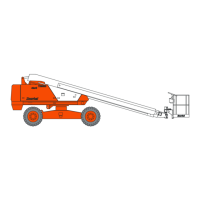
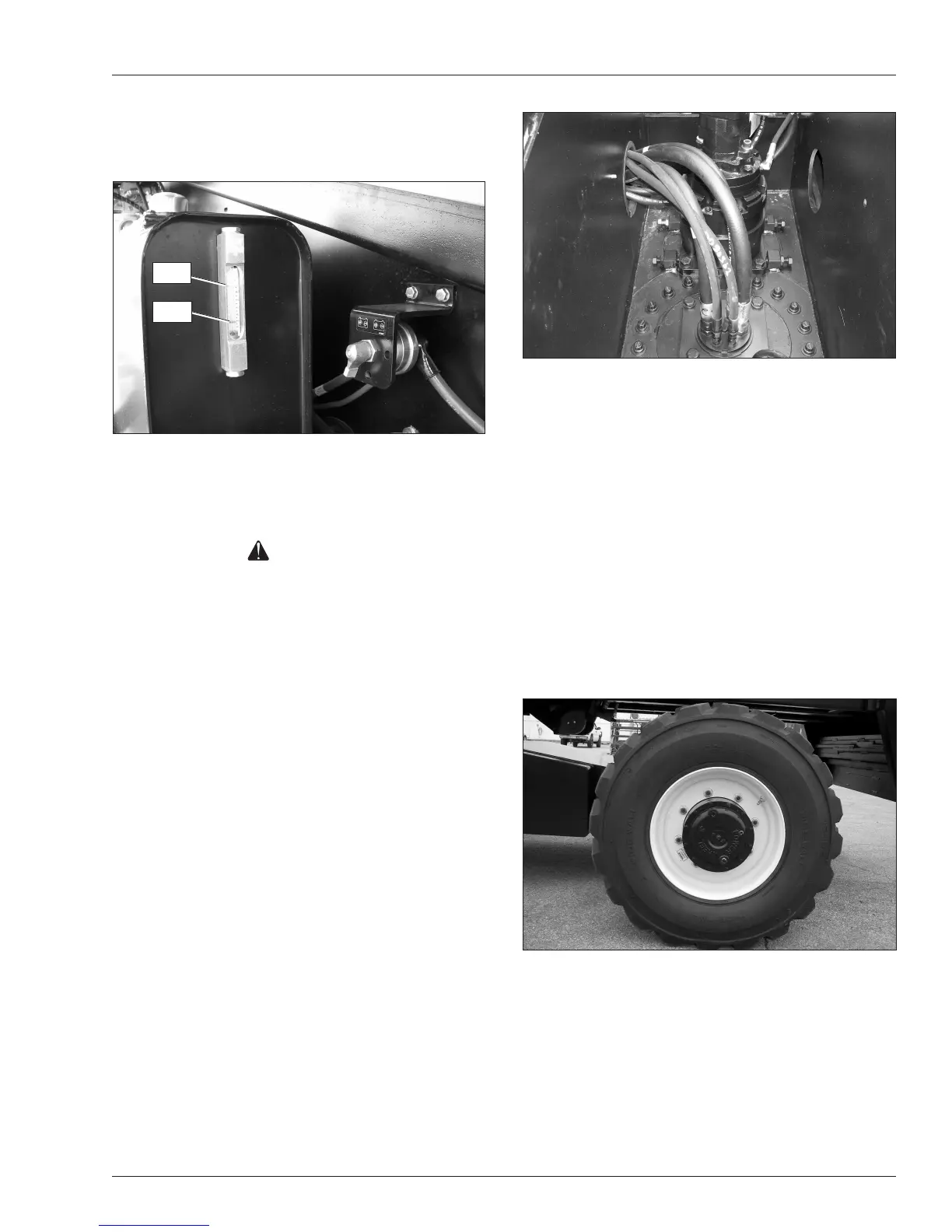
2. Open the door on the right side of the chassis to ac-
cess the hydraulic uid level gauge (refer to Figure
7.8).
Figure 7.8 – Hydraulic Fluid Gauge
3. Make sure the uid level is between the minimum
and maximum lines.
Caution
Not all hydraulic uid is suitable to use in the hy-
draulic system. Some have poor lubricating char-
acteristics and may increase component wear. Only
use hydraulic uid as recommended.
4. If necessary, remove the ller cap and add uid of
the proper type. Replace the cap making sure it is
tightly in place.
Note
Refer to Chapter 2 for the proper type and grade of
hydraulic uid to use. The need to regularly add uid
indicates a leak that should be corrected.
5. The sight glass on the reservoir has an internal
thermometer to measure the uid temperature. The
temperature should be less than 200°F (93°C).
Fluid Filter
Checking the condition of the hydraulic uid lter is part
of the machine maintenance schedule and should not
be performed by the operator.
Hoses, Tubes, and Fittings
To inspect the hoses, tubes and ttings:
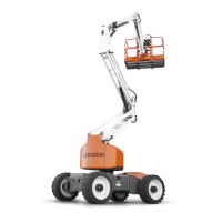
1. Inspect all hydraulic hoses, tubes, and ttings for
wear, leakage, or damage (refer to Figure 7.9).
Figure 7.9 – Hoses, Tubes, and Fittings
2. Make sure the hoses are properly routed to avoid
sharp edges, kinking, and scufng.
3. Inspect the tubes for dents or other damage that
may restrict uid ow.
4. Make sure all hoses and tubes are held rmly in
their support brackets.
5. Check under the chassis for uid that has leaked.
Hydraulic fluid leaks are easily visible on the
ground.
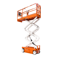
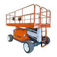
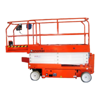
Tires and Wheels
Visually inspect the tires and wheels (refer to Figure
7.10) to make sure they are suitable for service.
Figure 7.10 – Tires and Wheels
Foam lled tires do not have a pressure decal or a
valve core.
To inspect foam lled tires and wheels:
1. Check the wheel lug nuts to see that none are miss-
ing, damaged, or loose.
Full
Add