V. INSTALLATION OF PROXIMITY READER:
1. Reader connections
:
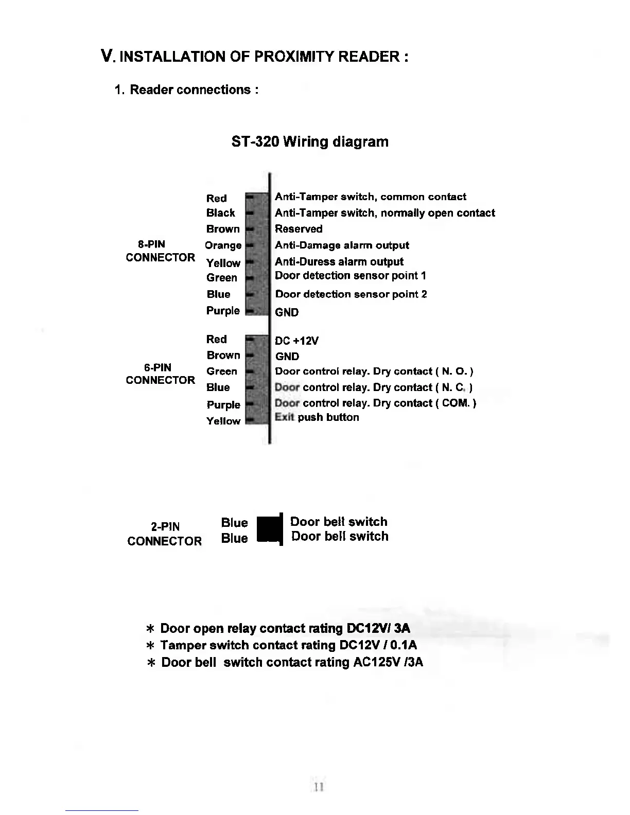
ST-320 Wiring diagram
Red
Black
Brown
8-PlN
Orange
CoNNECTOR
Yeilow
Green
Blue
Purple
Red
BJown
6-PlN
creen
coNNECTOR
Btue
Purple
Yellow
2-PIN
CONNECTOR
Anti-Tamper switch, common contact
Anti-Tamper switch, nom.lly open conlact
Roseffed
Anti-Damage
alarm output
Anti-Duress alarm oulput
Door detection *nsor
point
1
Door
detection sensor
point
2
GND
DC
+l2V
GND
Door control relay. Dry
contact
(
N. O.
)
control relay. Drycontact
(
N. C
)
cont.ol relay.
Dry
contact
(
COM.
)
push
button
Blue
Blue
I
mm*l""l
* Door opon relay contact Eting trclArr 3A
:*
Tamper switch contact Eting DCI2V / 0.lA
t( Door bell switch contact
rating
Acl25V
/3A