6.30
160
8.66
220
9.45
240
2.52
63,90
1.89
48,10
7.09
180
1
2
8.66
+/-0.4
220
+/-1
6.30
+/-0.4
160
+/-1
5.9
+/-0.4
150
+/-1
6.77 - 7
172 - 178
0.25
6,4
R 0.24
R 6,25
0.12
3
1.53
±0,01
39
±0,3
0.86
22,05
±0,02
15,5
±0,5
135°
0.07
2
0.31
±
8
±0,1
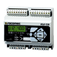
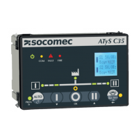
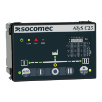
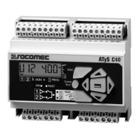
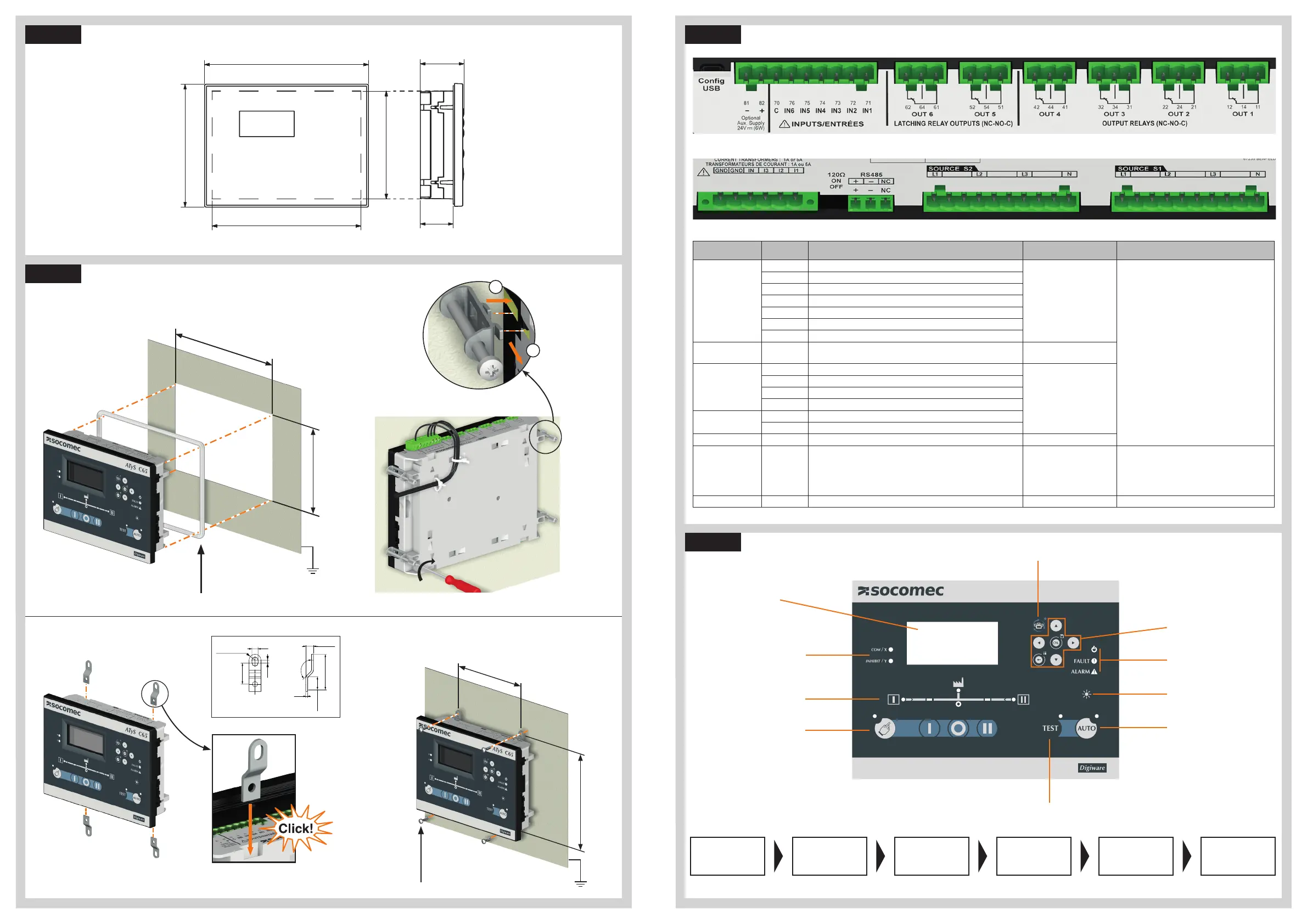
Gasket for IP 65
LCD display
Source and
switchsynoptic
Manual operation
buttons and
indicator
C65 programable LED
C55 LED COMM & Inhibit
Automatic
button and LED
indicator
Test button and indicator
Lamp test
button
Power, Fault and
alarm LED
Navigation
buttons
Change dashboard / set screen as
favorite
STEP 1A
STEP 1B
Product dimensions
Mounting & connecting controller
Door mounting
Backplate mounting
STEP 2
Controller wiring
When powered for the first time the controller will prompt the user to configure using the wizard.
To access the wizard input code 1000 then the configuration will go as follow:
SMART WIZARD CONFIG:
Foradvanced configuration go to parameters menu.
Language Source configTime & date
Switch &
Application
Product Name
Communication
STEP 3
Configuration
TYPE TERMINAL N° DESCRIPTION CHARACTERISTICS RECOMENDED CROSS SECTION
Inputs
71 IN1: programmable input
Do not connect to any power supply
from terminal 70 common point.
1.5-2.5mm²
AWG 16-14
Tightening torque
0.5-0.6 Nm
4.4-5.3 Lb.in
72 IN2: programmable input
73 IN3: programmable input
74 IN4: programmable input
75 IN5: programmable input
76 IN6: programmable input
70 Common point for inputs
Aux power supply 81/82
- : negative terminal for aux supply
+: positive terminal of aux supply
12-24 Vd.c.
Outputs
12/14/11 OUT1: reserved (switch ODR1)
Dry contacts
8A / 277 VAC 50/60 Hz
5A / 24 VDC
22/24/21 OUT2: reserved (switch ODR2)
32/34/31 OUT3: programmable output
42/44/41 OUT4: programmable output
Latching relays
52/54/51 OUT 5: programmable latching relay
62/64/61 OUT 6: genset start relay
Current transformers IN/I3/I2/I1 CT neutal / CT phase C / CT phase B/ CT phase A CT input 1A or 5A
Serial connection RS485
Connection RS485
-: negative terminal of RS485 bus
+: positive terminal of RS485 bus
NC : Ground
RS485 bus insulated
LiYCY sheilded twisted pair 0.14 to1.5 mm² / 30-14 AWG
Tightening torque
0,22 -0,25 Nm
1.9-2.2 Lb.in
Digiware* DIGIBUS Connection point for I/O 10 optional accessories (must use 24VDC input) RJ 45 digiware cable
* For more information check I/O module instruction sheet ref 545597
6.30
160
8.66
220
9.45
240
2.52
63,90
1.89
48,10
7.09
180
Dual Dimensions
in/mm
Screw Tightening torque
PH1 / 0.2 Nm / 1.77 lb.in
Screws notdelivered with product
Insert the 4 door
mounting screws in
thedesignated slot and
push back to lock in
place.
Example of cable way.
Clip the mounting feet in thedesignated slot
GND
GND
Bottom view
Top view
 Loading...