EasyManua.ls Logo

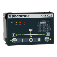
socomec ATyS C25 User Manual

socomec ATyS C25
38 pages
To Next Page IconTo Next Page
Page #1 background imageLoading...
Page #1 background image
www.socomec.com
To download, brochures, catalogues and technical manuals:
ATS Controller
ATySA15
INSTRUCTION MANUAL
EN

Questions and Answers:

socomec ATyS C25 Specifications

General IconGeneral
Current Rating25 A
Frequency50/60 Hz
Ith25 A
Ie AC2125 A
Ie AC2225 A
Ie AC2325 A
Rated Current25 A
Protection DegreeIP20
Control MethodAutomatic / Manual
Communication ProtocolModbus
Storage Temperature-40 to +85 °C

Summary

GENERAL SAFETY INSTRUCTIONS

Abbreviation and Terms

Defines abbreviations and terms used in the manual for clarity and understanding.

STANDARDS

INTRODUCTION

ATYS FAMILY PRODUCT RANGE

QUICK START

Mounting and Unmounting

Instructions for installing and removing the ATYS A15 controller.

HMI and Connection Diagrams

Explanation of the controller's HMI, LEDs, buttons, and connection diagrams.

Configuration and Technical Data

Details on DIP switch settings and technical specifications of the ATYS A15.

Connector Details

Identification and description of the controller's connectors.

GENERAL OVERVIEW

Product Identification

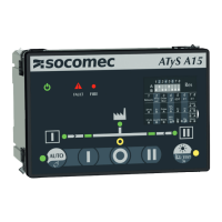
Identifies the main components and features of the ATYS A15 controller's front panel.

Controller HMI Functions

Detailed explanation of the ATYS A15 controller's HMI and LED indicators.

Environmental Requirements

Details IP rating, IK rating, operating conditions, EMC, altitude, and storage requirements.

Lead Free and RoHS Compliance

Information regarding compliance with RoHS and China RoHS directives for lead-free manufacturing.

WEEE and Pollution Class

Compliance with WEEE directive and specification of pollution class for the ATYS A15.

Other Compliances and Compatible Products

Lists other compliance marks and compatible accessories and RTSE products.

CONTENT OF PACKAGING

INSTALLATION

Product Dimensions

Provides the physical dimensions of the ATYS A15 controller.

Door Mounting Instructions

Instructions and specifications for mounting the ATYS A15 controller onto a door.

DIN RAIL Mounting Instructions

Instructions for mounting the ATYS A15 controller onto a standard DIN rail.

CONNECTIONS

Network Types

Describes the types of electrical networks (1P+N, 3P+N) the ATYS A15 can connect to.

Metering and Sensing Details

Details metering and voltage sensing configurations for different network types.

Controller Connection Terminals

Illustrates the TOP and BOTTOM connection terminals of the ATYS A15 controller.

Connection Diagrams with ATyS R

Provides specific connection diagrams for the ATYS A15 with ATYS R.

Terminal Denominations and Characteristics

Detailed table of terminal designations, descriptions, and electrical characteristics for the ATYS A15.

ATYS A15 OPERATING MODES

Auto Mode Operation

Describes the automatic operation mode of the ATYS A15 controller.

Manual Mode Operation

Explains the manual operation mode and how to switch to it.

Inhibit Mode Functionality

Details the inhibit mode, its activation, and its effect on controller functions.

Triple Power Supply Options

Information on the ATYS A15's ability to be supplied by three power sources (AC/DC).

Voltage Sensing Inputs

Explains voltage sensing inputs for monitoring network parameters like phase rotation and frequency.

Fixed Output Signals

Describes the fixed output signals provided by the ATYS A15 for control purposes.

Control Signal Outputs

Details the control signal outputs used for communication with the RTSE.

Genset Start Output

Explains the functionality of the genset start output relay.

Fixed Input Signals

Details the fixed input signals used for controlling the ATYS A15.

Inhibit Input Function

Describes the function of the inhibit input and its effect on the controller.

Position Input Feedback

Explains how position inputs from the RTSE are used for feedback.

Fire Input Activation

Details the fire input activation and its consequences on controller operation.

Controller Programming

Information on how to program the ATYS A15 controller.

DIP Switch Programming

Step-by-step guide for programming the controller using the front panel DIP switches.

CHARACTERISTICS

Electrical Specifications

Lists the electrical specifications of the ATYS A15 controller.

Mechanical Specifications

Lists the mechanical specifications of the ATYS A15 controller.

Communication Interfaces

Details the communication interfaces and protocols supported by the ATYS A15.

PREVENTIVE MAINTENANCE

TROUBLE SHOOTING GUIDE

ASSOCIATED PRODUCTS

RTSE Products Overview

Overview of associated SOCOMEC RTSE products (ATYS d M, ATYS S).

ATYS r Series

Details on the ATYS r series of transfer switches.

ANNEXE I

ATYS A15 HMI Reminder

A reminder illustration of the ATYS A15 controller's Human Machine Interface (HMI).

LED Indicator Functions

Explains the different states and behaviors of the ATYS A15 controller's LED indicators.

Connection Diagrams with ATYS S

Provides connection diagrams for the ATYS A15 with ATYS S.

Connections with ATyS dM

Illustrates the connection diagrams for the ATYS A15 with ATYS dM.

Connections with Standard CC TSE

Shows connection diagrams for ATYS A15 with standard CC type based TSE.

Phase Rotation Check

Explains the process of checking phase rotation between the two sources.

Voltage/Frequency Configuration

Details how to configure voltage and frequency levels via DIP switch or communication.

Timer Settings Overview

Overview of the various timers available in the ATYS A15 controller.

Fail and Return Timers

Configuration of source fail timers (FT) and source return timers (RT).

Cooldown Timer Function

Explains the cooldown timer function for generator start signals.

Dead Band Timer ODT

Details the dead band timer (ODT) for transfer between sources.

Priority Setting Configuration

Configuration of source priority settings using DIP switches or communication.

Test Functions

Describes the LED test and TEST ON LOAD functions using the HMI button.

A15 Operating Sequence

Illustrates the controller's operating sequences for source priority and DPS output.

Related product manuals