30
EN
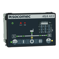
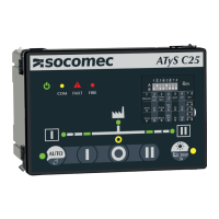
ATySController C25 - 549780A - SOCOMEC
15.1. LED Functioning modes
LED indicator
(cf image above
LED blinking LED ON** LED OFF*
1: Source 1 availability Source 1 present but not
available for following possible
reason:
- Source undervoltage /under
frequency
- Source overvoltage /over
frequency
- Phase rotation order of source 1
& 2 are different
Source is available Source is not available
2: Position I indicator
/
RTSE is in position I / Load is
connected to source 1
RTSE is not in position 1 / Load
is not connected to source 1
3: Position 0 indicator
/
RTSE is in position 0 / Load is
not connected to source 1 or
source 2
RTSE is in position 0 / Load is
not connected to either source 1
or source 2
4: Load supplied indicator
/
Load is being supplied by a
source which is available
Load is not being supplied by a
source which is available
5: Position I indicator
/
RTSE is in position II / Load is
connected to source 1
RTSE is not in position II / Load
is not connected to source 1
6: Source 2 availability Source 2 present but not
available for following possible
reason:
- Source undervoltage /under
frequency
- Source overvoltage /over
frequency
- Phase rotation order of source 1
& 2 are different
Source is available Source is not available
7: AUTO/MANUAL indicator
A timer is counting down and a
transfer will be initiated.
(If fault is blinking with buzzer
AUTO/MANU will be blinking)
The controller is in automatic
mode
Controller is not in automatic
mode possible modes :
-Manual
-Inhibited
-Fault detected
8: TEST led / Test is ongoing No test ongoing
10: Power / Controller is powered up Controller is OFF
11: Communication
Controller is sending / receiving
information
Communication parameters have
been modied (Baud rate / Parity
/ address)
No communications orders are
currently being sent or received
12 : Fault indicator Fast blinking (3Hz): one or more
Dip switch has changed and
conguration as not been saved.
Long blinking (2Hz): Inhibit input
is active or fault is active
/
Inhibit is not active / no faults
active and dip switch congura-
tion has been saved.
*Considering that the controller is powered.
**Considering that lamp TEST has not been initiated
 Loading...