
J
Joseph ChambersAug 19, 2025
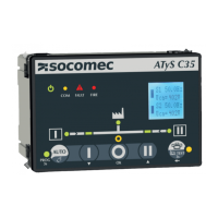
What to do if the Alarm LED is blinking on my socomec ATyS C35 Controller?
- MMaria EllisSep 12, 2025
If the Alarm LED is blinking on your Socomec Controller, it indicates a potential issue. First, verify that input 90-91 or any other input programmed to FAULT or NOT IN AUTO is not active. Also, check if there was a problem during a transfer order and validate the fault using the AUTO button. Finally, ensure that there are no ongoing faults.