8
EN
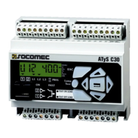
ATySController C35 - 549781A - SOCOMEC
5. QUICK START
106
1,5 - 3
144
(0/+1)
92
(0/+0 ,8)
1
2
312 313 314 315316 317 63A64A 24 14 04 13
- +
36 35 943751 54 52 F1 73 72F2 71 70
1413 15 16 17
103
102 101 302 301 202 201
104
105
106 203 204 205
206
93 92 91
L1
L2
L3
N
L1
L2
L3
N
318-520 ph-ph
184-300 ph-n
318-520 ph-ph
184-300 ph-n
NC + - 0 I I I C
Ctrl OFF I I
I I
I
I
0
0
C
C
-
+
I I
81 82
I 0 C
Aux supply
SOURCE 1
S1 IN S2 IN
DPS OUT
All fuses 4A type gG*
*Using a Socomec cable harness kit excludes the need for fuses
SOURCE 2
301 302
X2
HMI Programming
Connection with ATyS
Connectors
Dashbord orderTechnical characteristics
Mounting
To access the programming mode do a long press on button 14 and enter the password
(Default 1000).
Menu Submenu Adjustment range Default value Description
System NETWORK 1P+N, 2P, 3P, 3P+N 3P+N Select the installation network type.
NOM. VOLT. 220Vph-N, 230Vph-n,
240Vph-N, 380Vph-ph,
400Vph-ph, 415Vph-ph
400Vph-ph
(4)
Network nominal voltage.
NOM. FREQ. 50, 60 Hz 50Hz Network nominal frequency
APP S1-Mains S2-Gens,
S1-Gens S2 – Mains,
S1-Mains S2 – Mains
S1-Mains
S2-Gens
Type of application.
TECHNO
TYPE
PC Type, CC Type,
CB Type
PC Type Type of RTSE technology.
SIGNALTIME 0.1s-20s , MAINT 5.0s Duration of the signal time (when CC
type is selected the signal time is always
maintained).
PRIO NET S1, S2 S1 Priory source settings, the controller prioritize
the source selected.
RETURNS AUTO RESTRANS,
MANU RETRANS, NO
RETRANS
AUTO
RESTRANS
Retransfer mode, automatic, manual
retransfer (needs user validation before
transferring to priority source), or no
retransfer (controller will not retransfer
automatically to the priority source).
ROT PH L1L2L3, L3L2L1, OFF OFF Selection of the rotation order of phases,
when “OFF” is selected controller will not
check the phase rotation order.
COM Contains submenu for all RS485, Modbus settings cf. communication settings.
PASSWORD 0000-9999 1000 Password for required access settings
such as mode change, test launch and
programing.
BACKLIGHT Keep-Active, 30min-
1min
Keep-Active Duration of the backlight on LCD screen
(If the product is using 24VDC only to
power backlight will be off).
Language
ENGLISH, 中文,
English Controller language.
ABOUT NA NA Show software version, and serial
number.
RST.
FACTORY
NA N/A Press “OK” in this menu to reset all
settings to default values.
Voltage
(1)
S1-OVth 120-102% 115% Over voltage threshold for loss of source 1
(must be greater than hysteresis setting).
S1-OVhy 119-101% 110% Over voltage hysteresis for return of
source 1 (must be inferior to threshold
setting).
S1-UVth 98-80% 85% Under voltage threshold for loss of
source 1 (must be inferior to hysteresis
setting).
S1-UVhy 99-81% 95% Under voltage hysteresis for return
of source 1 (must be greater than to
threshold setting).
S2-OVth 120-102% 115% Over voltage threshold for loss of source
2 (must be greater than hysteresis
setting).
S2-OVhy 119-101% 110% Over voltage hysteresis for return of
source 2 (must be inferior to threshold
setting).
S2-UVth 98-80% 85% Under voltage threshold for loss of
source 2 (must be inferior to hysteresis
setting).
S2-UVhy 99-81% 95% Under voltage hysteresis for return
of source 2 (must be greater than to
threshold setting)
S2-UVhy 99-81% 95% Under voltage hysteresis for return
of source 2 (must be greater than to
threshold setting)
Frequency
(2)
S1-OFth 120-102% 115% Over frequency threshold for loss
of source 1 (must be greater than
hysteresis setting).
S1-OFhy 119-101% 110% Over frequency hysteresis for return of
source 1 (must be inferior to threshold
setting).
S1-UFth 98-90% 90% Under frequency threshold for loss of
source 1 (must be inferior to hysteresis
setting).
S1-UFhy 99-91% 95% Under frequency hysteresis for return
of source 1 (must be greater than to
threshold setting).
S2-OFth 120-102% 115% Over Frequency threshold for loss
of source 2 (must be greater than
hysteresis setting).
S2-OFhy 119-101% 110% Over frequency hysteresis for return of
source 2 (must be inferior to threshold
setting).
S2-UFth 98-90% 90% Under frequency threshold for loss of
source 2 (must be inferior to hysteresis
setting).
S2-UFhy 99-91% 95% Under frequency hysteresis for return
of source 2 (must be greater than to
threshold setting).
Timers S1-FT 3-60s 5s Source 1 fail timer.
S2-FT 3-60s 5s Source 2 fail timer.
S1-RT 3-3600s 5s Source 1 return timer.
S2-RT 3-3600s 5s Source 2 return timer.
S1-S2 0DT 0-20s 0s Source 1 dead band timer.
S2-S1 0DT 0-20s 0s Source 2 dead band timer.
CT 0-3600s 180s Generator Cool down timer.
SD 0-6000s 0s Generator start delay.
ST 1-3600s 30s Generator start timeout timer.
Test BUTTON
TEST
Test on load,
Test off load
Test on load Test mode for the HMI test button.
LCD TEST Starts a lamp test and LCD test.
In/Out IN. FUN1 See full manual NOT IN AUTO Input function for input 1 (91-92).
IN. TYPE 1 NO, NC NC Input type.
IN. DELAY. 1 0.01-60.00s 0.05 Input delay timer.
IN. FUN 2 See full manual NONE Input function input 2 (91-93).
IN. TYPE 2 NO, NC NO Input type.
IN. DELAY. 2 0.01-60.00s 0.05 Input delay timer.
IN. FUN 3 See full manual NONE Input function input 3 (91-92).
IN. TYPE 3 NO, NC NO Input type.
IN. DELAY. 3 0.01-600.00s 0.05 Input delay timer.
OUT. FUN1
(3)
See full manual GENSET Output function for programmable output.
OUT. TYPE 1
(3)
NO, NC NC output type.
(1) % of Voltage set in “NOM VOLT” must be within the working limits of the controller 184-300 V.a.c P-N.
(2) % of Frequency set in “NOM FREQ”.
(3) Only congurable when “APP” is set to S1-Mains S2-Mains.
(4) If voltage is set to 1PH+N the default value for NOM. VOLT. Will automatically be set to 230Vph-n.
dimensions in mm.
Connectors top view
Connectors bottom view
Denomination Terminal Description Characteristics
Control signal
outputs (orders
to RTSE)
13 Not used / Source 2 open
AC1 – General use – Ie: 5A , Ue: 250 V.a.c
DC1 – General use – Ie: 5A , Ue: 30 V.d.c
AC15 - Ie: 3A, Ue: 120 V.a.c
AC15 - Ie: 1.5A, Ue: 240 V.a.c
DC13 - Ie: 0.22A, Ue: 125 V.d.c
DC13 - le: 0.11A, Ue: 250 V.d.c
14 Position II order / Source 2 closed
15 Position I order / Source 1 open
16 Position 0 order / Source 1 closed
17 Common point for position output
RS485
35 NC – Not connected
RS485 Isolated bus36 Negative electrode
37 Positive electrode
Genset output
51 Common point
52
Closed to start the Genset (closed when
controller is powered off)
AC1 – General use – Ie: 3A , Ue: 250 V.a.c
DC1 – General use – Ie: 3A , Ue: 30 V.d.c
AC15 - Ie 54/51: 3A 52/51: 1.5A Ue: 120 V.a.c
AC15 - Ie 54/51: 1.5A 52/51: 0.75A Ue: 240 V.a.c
DC13 - Ie 54/51: 0.22A 52/51: 0.22 A 125 V.d.c
DC13 - Ie 54/51: 0.11A 52/51: 0.11 A 250 V.d.c
54 Open to start the genset
Controller
programmable
inputs
91 Common point for programmable inputs
Do not use external voltage
Power from common point
92
Programmable input 1 (Set as default to
«NOT IN AUTO»)
93 Programmable input 2
94 Programmable input 3
Return of
information from
RTSE (Position
inputs)
70 Common point for position inputs
Do not use external voltage
Power from common point
71 Position I RTSE
72 Position II RTSE
73 Position 0 RTSE
Fire input
F1 Negative electrode of the d.c power source
12-24 V.d.c
F2 Positive electrode of the d.c power source
Optional Aux
supply 24V.d.c
81 Negative electrode of the d.c power source
10-30 V.d.c (Auxiliary supply for controller, does not
supply RTSE)
82 Positive electrode of the d.c power source
Source 1 and 2
voltage inputs
103 Source 1 N
Sensing range:
90-520 V.a.c (ph-ph)
50-300 V.a.c (ph-n)
45-65 Hz
Supply:
184-300 V.a.c* (ph-n)
45-65 Hz
Max consumption 10 W
*200-300 V.a.c in maintained mode
104 Source 1 L1
105 Source 1 L2
106 Source 1 L3
203 Source 2 N
204 Source 2 L1
205 Source 2 L2
206 Source 2 L3
DPS output
(RTSE power
supply)
301 Phase output
AC – General use – Ie: 6A , Ue: 250 V.a.c
DC – General use – Ie: 6A , Ue: 30 V.d.c
AC15 - Ie: 3A, Ue: 120 V.a.c
AC15 - Ie: 1.5A, Ue: 240 V.a.c
DC13 - Ie: 0.22A, Ue: 125 V.d.c
DC13 - le: 0.11A ,Ue: 250 V.d.c
302 Neutral output
Voltage / frequency settings
DIN rail mounting
1. Mounting
2. Unmounting
Door mounting (IP 40)
IEC 60715
DIN rail
1
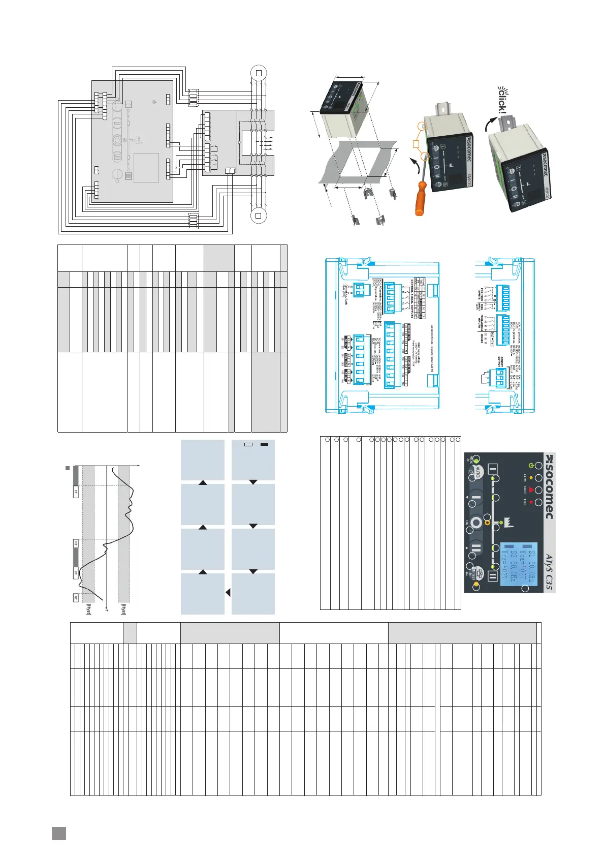
Auto LED (Green fixed when in auto mode, green blinking when transfer or fault ongoing).
2
Source 1 availability information (green fixed when source 1 is present and available and within threshold
limits, green blinking when source 1 is present but outside of threshold limits, off when under 50VAC).
3
Switch 1 LED position indications (green fixed when in position 1).
4
Zero position LED indication (yellow when in position 0).
5
Load supplied information (green fixed when load is supplied by an available source) green blinking when
load is supplied with a source which is present but outside of threshold limits).
6
Switch 2 LED position indications (green fixed when in position 2).
7
Source 2 availability information (green fixed when source 2 is present and available and within threshold
limits, green blinking when source 2 is present but outside of threshold limits, off when under 50VAC).
8
Test LED (yellow fixed when a test ins ongoing or when in programming mode).
9
Run LED (Green when product is powered).
10
COM LED (yellow blinking when RS communications is ongoing).
11
Fault LED (red blinking – long blink when fault or inhibit is activated).
12
FIRE LED (red fixed when fire input is activated).
13
Multi line LCD screen.
14
AUTO/MANU/PROG button, short press (<3s) to switch between AUTO and MANU modes then add
operator password to confirm (1000 default value). Long press (>3s) on this button to enter the programming
mode.
15
DASHBOARD/TEST button, short press (<3s) to change the dashboard shown (7 screens) (after 30s will
reset to default dashboard. A long press (>3s) will start a TEST ON LOAD, to validate enter the operator
password (1000 default). To stop the test, long press on this button again.
16
DOWN/POS1 button, in MANU mode will switch to position 1. In programming mode or when password is
requested, go up in the menu screen.
17
OK/POS0 button, in MANU mode will switch to position 0. Use to validate selection in programming mode or
when a password is requested.
18
UP/POS2 button, in MANU mode will switch to position 2. In programming mode or when password is
requested, go down in the menu screen
Source available
U/F
OVth/OFth
OVhy/OFhy
Unom/Fnom
UVhy/UFhy
UVth/UFth
8
2
3
4
5 6 7
1
9 10 12
13
14
17 15
1816
11
S1=OVth=116%
S1=OVhy=110%
S1=UVth=85%
S1=UVhy=95%
S2=OVth=112%
S2=OVhy=110%
S2=UVth=85%
S2=UVhy=95%
POS. I COUNT
00016
POS. II COUNT
00010
S1-S2
Phase angle
-10°
S1=OFth=116%
S1=OFhy=110%
S1=UFth=90%
S1=UFhy=95%
S2=OFth=112%
S2=OFhy=110%
S2=UFth=90%
S2=UFhy=95%
S1=RT=0005s
S1=FT=05s
S2=RT=0005s
S2=FT=04s
S1-S2=0DT=00s
S2-S1=0DT=01s
SD=0000s
CT=0180s ST=0030s
INPUTS
71 POS I OFF
72 POS II ON
73 POS 0 OFF
92 OFF
93 OFF
94 OFF
OUTPUTS
16 POS I OFF
15 POS II ON
14 POS 0 OFF
13 OFF
52 OFF
S1 50.1Hz
U1n=232V
S2 50.2Hz
U1n=234V
 Loading...