10
EN
ATySController C35 - 549781A - SOCOMEC
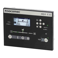
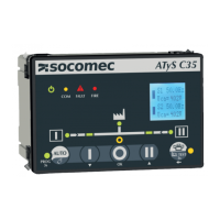
6.2. Controller HMI
2 3 4 65 7
8
12
9
1
10
11
1. Auto LED, led on if the controller is in automatic mode.
2. Source 1 availability information (Green xed when source 1 is present and available within threshold limits and all timers
nish counted, green blinking when source 1 is present but outside of threshold limits, off when under 50VAC).
3. Switch 1 LED position indication (Green xed when in position 1, green blinking when awaiting for position 1 conrmation).
4. Zero position LED indication (Yellow when in position 0, yellow blinking when awaiting for position 0 feedback indication).
5. Load supplied information (Green xed when load is supplied by an available source).
6. Switch 2 LED position indications (Green xed when in position 2, green blinking when awaiting for position 2 feedback indication).
7. Source 2 availability information (Green xed when source 2 is present and available within threshold limits, green blinking
when source 2 is present but outside of threshold limits, off when under 50VAC).
8. Test LED (Yellow xed when test on load is ongoing or when controller is in programming mode).
9. Run LED (Green when product is powered).
10. COM LED (Yellow blinking when RS communication is ongoing).
11. Fault LED (Red blinking – Long blink when fault or product is inhibited).
12. Fire (Red when re input is activated).
See Annex I for more details on the LED indicators.
 Loading...