
L
larry44Sep 9, 2025
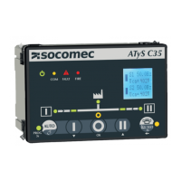
What does 'POS2 ERROR' mean on socomec ATyS C35 Controller?
- JJulie Gonzales PhDSep 9, 2025
If your Socomec Controller displays 'POS2 ERROR', it means the controller ordered a move to position 2, but it wasn't reached. Check the I/O connections and make sure the output signal time matches the RTSE being used.