Wire EDM Machine Operation Chapter 7
Copyright November, 98 Page 7-4 Sodick Inc.
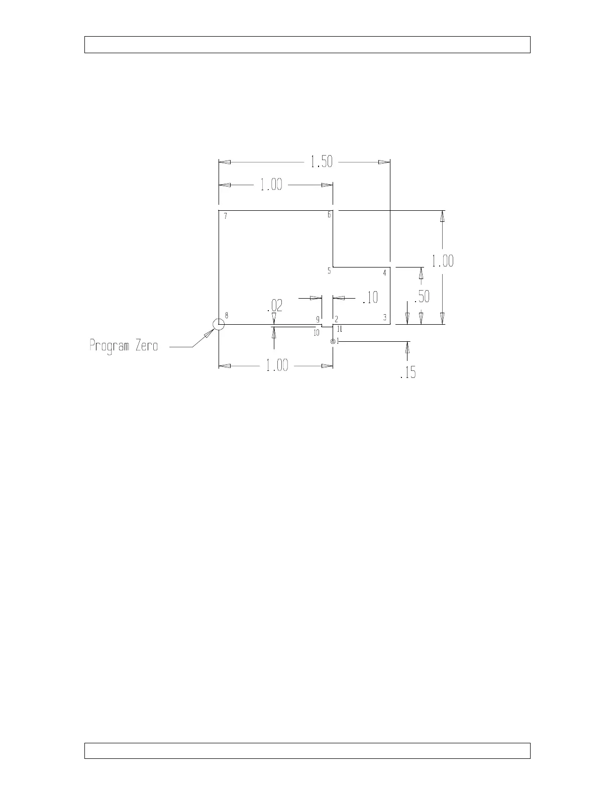
Now let’s put it all together. Figure 7-3 is the drawing for a sample program that shows
how to program wire radius compensation correctly. Note the method by which the
compensation is instated and canceled. This example is showing the method of using wire
radius compensation and makes no trim passes.
Figure 7-3
Program:
N005 G54 (SELECT COORDINATE SYSTEM NUMBER ZERO)
N010 G92 X1. Y-.15 (SET PROGRAM ZERO)
N015 G90 (SELECT ABSOLUTE MODE)
N020 G42 H061 (SELECT WIRE RIGHT AND .0061 OFFSET VALUE)
N025 C411 (SELECT MACHINING CONDITION)
N026 T91 ( AUTO WIRE THREAD)
N030 G01 Y0 (MOVE TO POINT 2)
N035 X1.5 (MOVE TO POINT 3)
N040 Y.5 (MOVE TO POINT 4)
N045 X1. (MOVE TO POINT 5)
N050 Y1. (MOVE TO POINT 6)
N055 X0 (MOVE TO POINT 7)
N060 Y0 (MOVE TO POINT 8)
N065 X.9 (MOVE TO POINT 9)
N070 G40 Y-.02 (MOVE TO POINT 10 AND CANCEL COMP.)
N075 M00 (PROGRAM STOP TO APPLY MAGNETS)
N080 G01 X1. (MOVE TO POINT 11 TO CUT OFF)
N085 Y-.15 (MOVE BACK TO START POINT)
N090 M02 (END OF PROGRAM)