SOFAR 1.1K~3.3KTL-G3 User manual
Copyright © Shenzhen SOFARSOLAR Co., Ltd
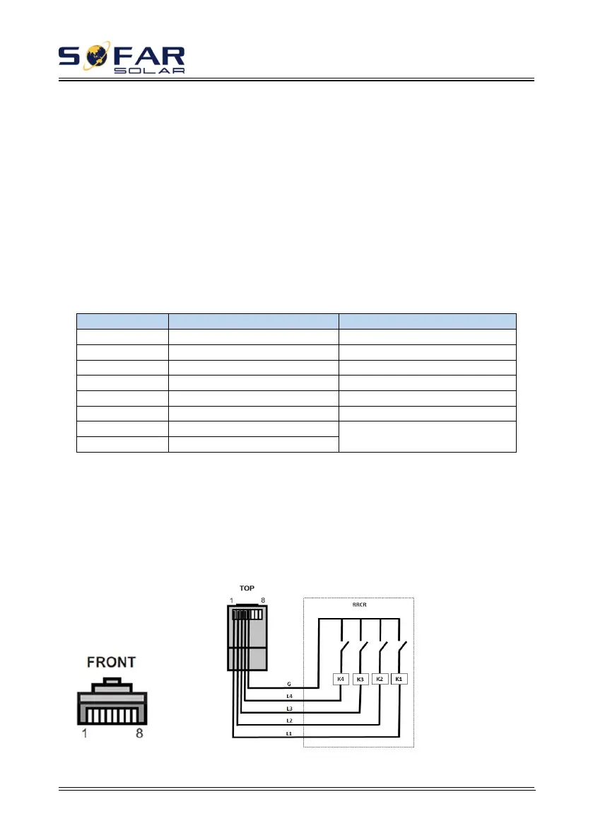
The logic interface pin definitions and circuit connections are as follows:
The function of logical interface needs to be set on the display screen, please
refer to the operation steps in section 6.3 .
Logic interface pin are defined according to different standard requirements.
(a) Logic interface for AS/NZS 4777.2:2015, also known as inverter demand
response modes (DRMs).
The inverter will detect and initiate a response to all supported demand
response commands within 2 s. The inverter will continue to respond while the
mode remains asserted.
Table 4-5 Function description of the DRMs terminal
NOTE: Supported DRM command: DRM0, DRM5, DRM6, DRM7, DRM8.
(b) Logic interface for VDE-AR-N 4105:2018-11, is in order to control
and/or limit the inverter’s output power.
The inverter can be connected to a RRCR (Radio Ripple Control Receiver) in
order to dynamically limit the output power of all the inverters in the installation.
Figure 4-28 Inverter – RRCR Connection