SOFAR 1.1K~3.3KTL-G3 User manual
Copyright © Shenzhen SOFARSOLAR Co., Ltd
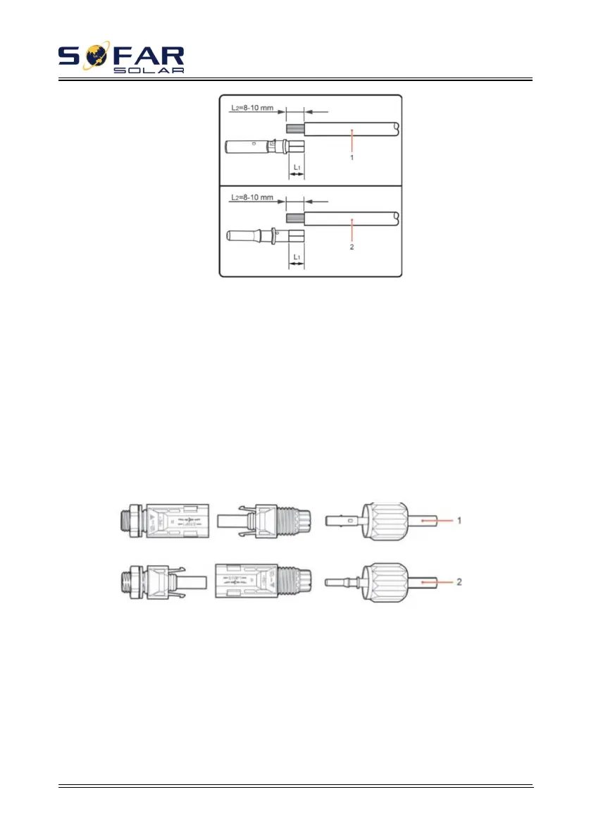
1.Positive power cable 2.Negative power cable
Note: L2 is 2 to 3 mm longer than L1.
Step 3 Insert the positive and negative power cables into corresponding cable
glands.
Step 4 Insert the stripped positive and negative power cables into the positive
and negative metal terminals respectively and crimp them using a clamping tool.
Ensure that the cables are crimped until they cannot be pulled out by force less than
400 N, as shown in Figure 4-6.
Figure 4-6 Connecting DC input power cables
1.Positive power cable 2.Negative power cable
Step 5 Insert crimped power cables into corresponding housings until you hear
a "click" sound. The power cables snap into place.
Step 6 Reinstall cable glands on positive and negative connectors and rotate
them against the insulation covers.
Step 7 Insert the positive and negative connectors into corresponding DC