Installation
5
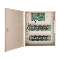
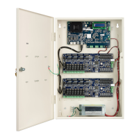
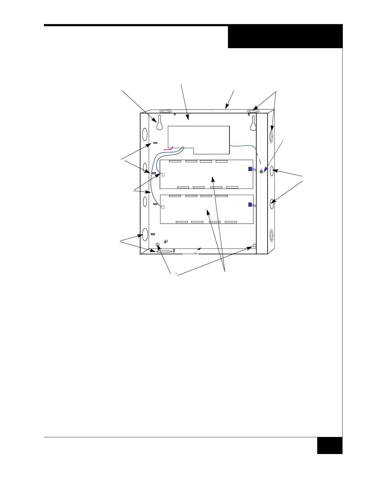
Figure 1. iSTAR Ultra SE Controller with Door Removed (Two ACMs Mounted)
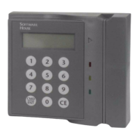
LCD
5. Align the mounting keyhole slots at the upper back of the enclosure with the
two upper mounting screws, and lower the enclosure into position.
6. After the enclosure is mounted tighten the mounting screws.
7. Install the two lower mounting screws.
8. Attach the conduit couplings to the knockout openings as needed to comply
with local code requirements.
9. Reattach the grounding wire between the door and the enclosure.
10.Connect to a grounding lug with a low impedance cable going to Earth
Ground.
11. When routing signal cables from the ACM to accessory boards on the door,
ensure that the cables are not pinched by the door and cables are routed in
accordance with NEC Codes or the applicable Local codes.
Ground Stud
(6-32)
For Shield Wire,
1 By Each Knockout
Assorted Knockouts
Cabinet/Enclosure
General Controller
Module (GCM)
Access
Control
Module
(ACM)
Assorted
Knockouts
Keyhole
Mounting
Slot (2)
Lower Mounting
Hole (2)
Tamper Switch
Assorted
Knockouts
USB Cables
ACM 1
ACM 2
GCM
E-Net
Tamper
LCD
LCD
Reader & Logic Power
Reader & Logic Power
 Loading...