Do you have a question about the Software House iSTAR Ultra and is the answer not in the manual?
Details the GCM, its operating system, and key features.
Describes the ACM's function, interfaces, and capabilities.
Ensures site readiness for installation and wiring according to regulations.
Provides physical dimensions and mounting hole specifications.
Guidelines for handling components safely to prevent electrostatic discharge damage.
Details the process and requirements for mounting the unit to a wall.
Specifies proper grounding procedures according to NEC and local codes.
Details input and output power specifications for the General Controller Module.
Details input and output power specifications for the Access Control Module.
Notes on over-current protection and circuit breaker sizing.
Details on connecting Ethernet ports (J5, J6) for network connectivity.
Explains the GCM's soft reset (SW7) and hard reset (SW2) functions.
Describes the functions of the 16-position rotary switch (SW3) for diagnostics.
Explains the Customer Proprietary Network Information mode switch setting.
Details the function of the RS-485 terminator switches for signal integrity.
Explains the wiring and function of the AC Fail and Low Battery input connections.
Explains ACM MCU reset (SW10) and RS-485 terminator switch settings.
Describes jumper settings for configuring ACM output relays as Wet or Dry.
Explains how to configure primary relays for activation by the FAI signal.
Details connections for USB, Tamper, Reader Power (J4), and LOCK 1 Power (J2).
Wiring instructions for FAI and Key signals using supervised resistors.
Direct connection details for Wiegand signaling readers.
Notes on using normal RM bus wiring for RM readers and boards.
Describes the 24 onboard inputs and their availability in sets of three.
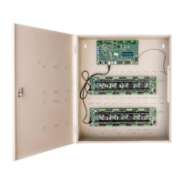
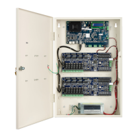
Lists product part numbers, subassemblies, and enclosure options.
Information regarding C-CURE, Software House trademarks, and copyright notices.
| Model | iSTAR Ultra |
|---|---|
| Type | Controller |
| Input Voltage | 12-24 VDC |
| Door Capacity | 8 |
| Max Users | 100, 000 |
| Cardholder Capacity | 100, 000 |
| Outputs | 8 |
| Processor | ARM Cortex-A9 |
| Operating System | Linux |
| Network Interfaces | 10/100 Ethernet |
| Communication | RS-485 |
| Max Doors Supported | 8 |
| Reader Capacity | 16 |
| Operating Temperature | 0°C to 49°C (32° to 120° F) |
| Memory | 512 MB RAM |
| Transaction Storage | 100, 000 |
| Inputs | 16 |
| Power Supply | 12V DC |
| Humidity Range | 0% to 95% non-condensing |
| Certifications | CE, FCC |