Access Control Module
24
FAI on this ACM - SW31
There are identical FAI controls on all ACMs. Set this switch to ON on the ACM
that is sensing the FAI and KEY signals. Set the switch to OFF on the other
ACMs.
Enable FAI Latch - SW30
If FAI Latch is true, all relays that have Activate on FAI true, will latch and
remain latched until the KEY signal resets them
Ports and Connectors
USB - J1
USB cable connection to the GCM.
Tamper - J22
The NC Tamper is connected to the GCM. Do not connect it here.Place a
jumper across the two pins and be sure the ACM Tamper is not configured in
the C•CURE software.
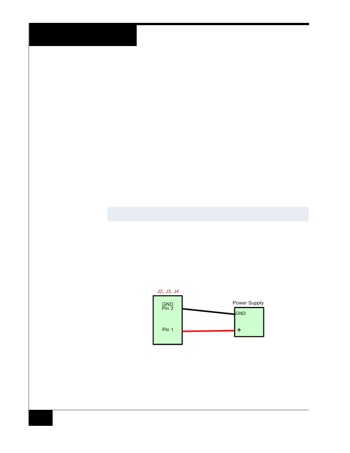
Reader Power - J4
This is the primary power input to the ACM. (12 Vdc @ 0.5 to 12.5 Amps max)
When connecting power to J2, J3, or J4, observe polarity as indicated in
Figure 9. The plus (+) is located on the bottom pin.
Figure 9. Reader Power - Observing Polarity
LOCK 1 Power - J2
This is one of the power inputs to the relay outputs that are jumpered as Wet
LOCK 1.
It can be either 12 Vdc or 24 Vdc. It will also supplement the J4 Reader Power.
NOTE
Shielded cable must be used for AC fail and Low Battery Input connections.