Installation
4
INSTALLATION
This section assumes that the site meets the requirements.
The iSTAR Ultra does not include mounting hardware. See Tab le 2 on page 3
for more detail.
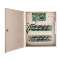
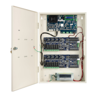
Wall Mount Installation
The most common installation is the wall mount. In this installation, the
enclosure is mounted directly to a wall or uni-strut using suitable user-supplied
hardware. See Tab l e 2 on page 3 for more detail.
Requirements:
The anchoring system must be capable of sustaining 75 lb (34 kg). This
weight does not include the cables.
The cables are protected by use of conduit, which is metal, plastic, or
flexible.
ACM cabling must be shielded.
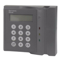
An external power supply provides 12 Vdc to run the logic of the iSTAR and
the read heads. There is an option for two external power supplies to supply
the locks using wet relays. The lock power supplies are rated at 0 - 30 Vdc,
but are usually 12 Vdc or 24 Vdc. In some installations, the locks can be two
12 Vdc or two 24 Vdc, or either combination of both voltages.
If an ACM is powered by a different PSU, the ACM Fail trigger must be
configured to alarm on failure.
The enclosure has knock-outs for installing and removing wires in and out of
the wall mount enclosure.
The enclosure door supports up to four accessary boards (I/8, I/8-CSI, R/8,
RM-4E), see
ELECTROSTATIC SENSITIVE DEVICES: Observe precautions for handling.
Before handling any internal components, discharge static electricity by
holding a grounding lug or non-painted surface for three seconds.
Wear a grounding wrist strap and stand on a grounded static mat.
Reduce movement during installation to reduce static buildup.
Make sure work area is safeguarded.
Transport components in static-shielded containers.
Note: The outside of the ESD bags are not ESD protective.
Verify that all components, materials, and the installer are referenced to a
common ground.