Installation
5
To Wall Mount the Controller:
1. Carefully unpack the components. Software House recommends removing
the GCM and the ACM(s) from the enclosure before mounting. Use ESD
procedures while handling the boards.
2. Open the enclosure door and disconnect the grounding wire on the door.
3. Carefully lift the door off the hinges, and place it on a padded surface.
4. Verify that the upper mounting screws (or equivalent) are in place on the
mounting site for the keyhole locations.
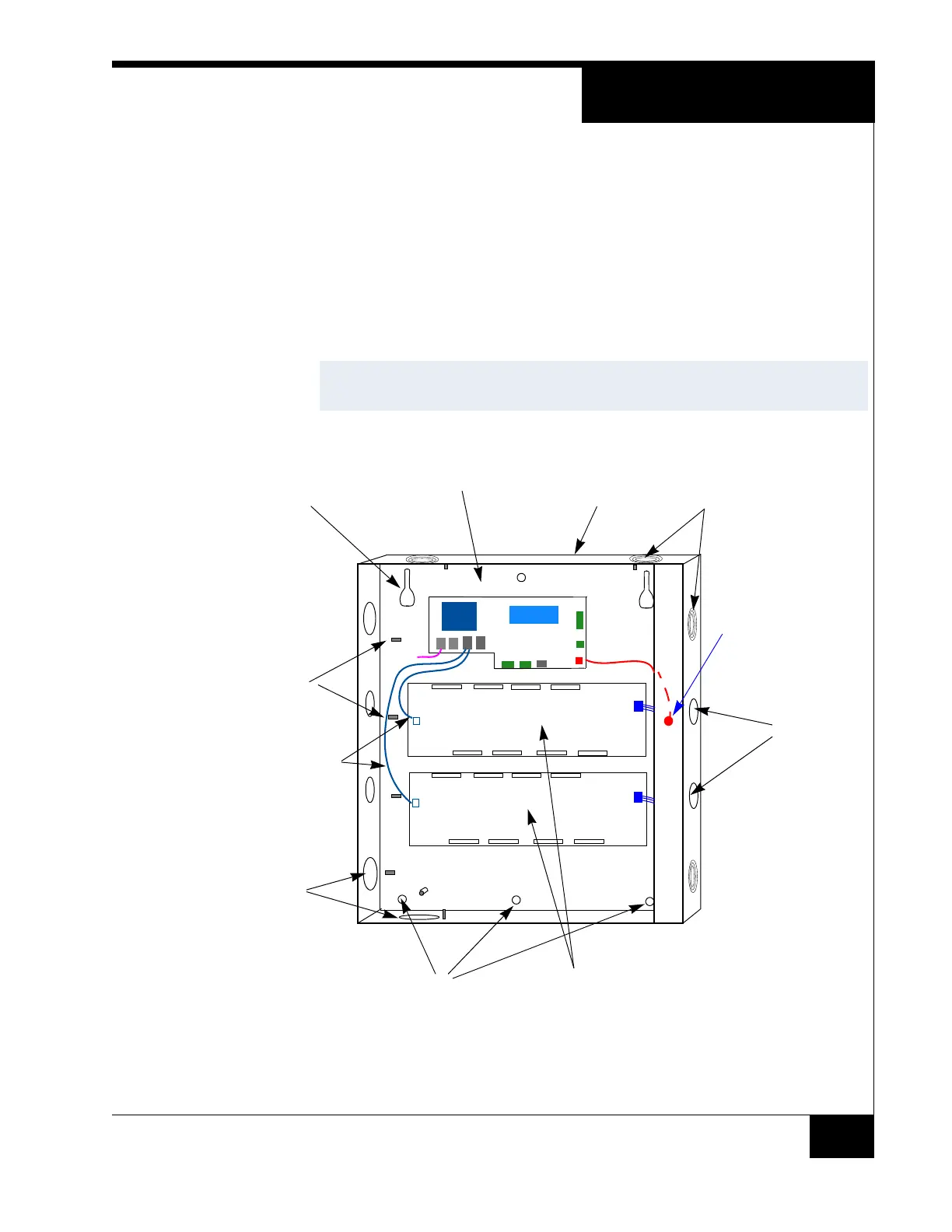
Figure 1. iSTAR Ultra Controller with Door Removed (Two ACMs Mounted)
LCD
5. Align the mounting keyhole slots at the upper back of the enclosure with the
two upper mounting screws, and lower the enclosure into position.
NOTE
See Figure 1 on page 5 for the location of the keyhole slots, screws, and
knockouts.
Ground Stud
(6-32)
For Shield Wire,
1 By Each Knockout
Assorted Knockouts
Cabinet/Enclosure
General Controller
Module (GCM)
Access
Control
Module
(ACM)
Assorted
Knockouts
Keyhole
Mounting
Slot (2)
Lower Mounting
Hole (3)
Tamper Switch
Assorted
Knockouts
USB Cables
ACM 1
ACM 2
GCM
E-Net
Tamper
LCD
LCD
Reader & Logic Power
Reader & Logic Power
Note: ACM Lock
Power IN supplies
the WET relay outputs.