Access Control Module
22
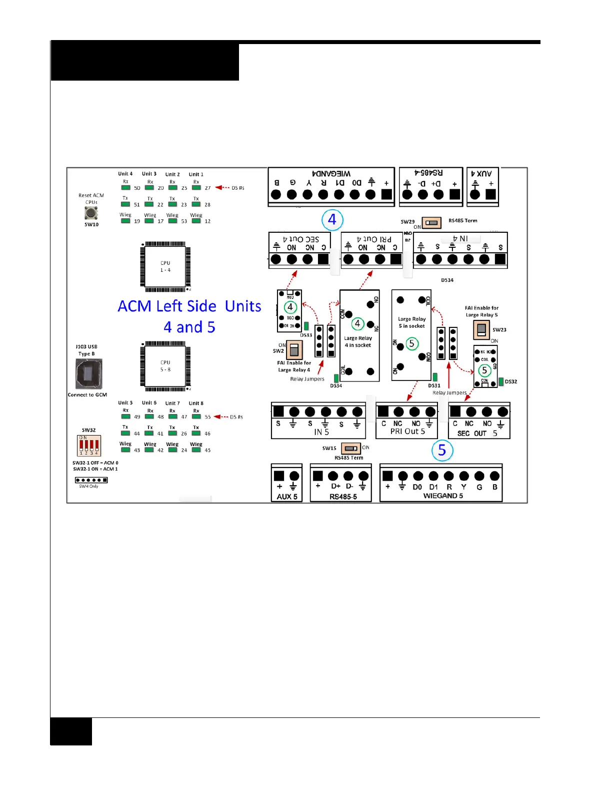
Figure 7 on page 22 shows the other end of the ACM and locates the USB client
connector, ACM Reset, and some of the LED locations. Sections 4 and 5 are
shown here.
Figure 7. ACM - Left Side
Switches and Jumpers
SW10 - ACM MCU Reset
SW10 reboots both MCUs. It should only be used when it seems the ACM is not
responding.
RS - 485 Terminators
SW12, SW14, SW28, SW29, SW15, SW25, SW24, SW27
These switches are set to ON by default, and are not usually changed. Setting
the switch to OFF places the RS-485 port in the middle of the RS-485 chain,
which allows the technician to connect two sections of a reader bus to this point.