Access Control Module
21
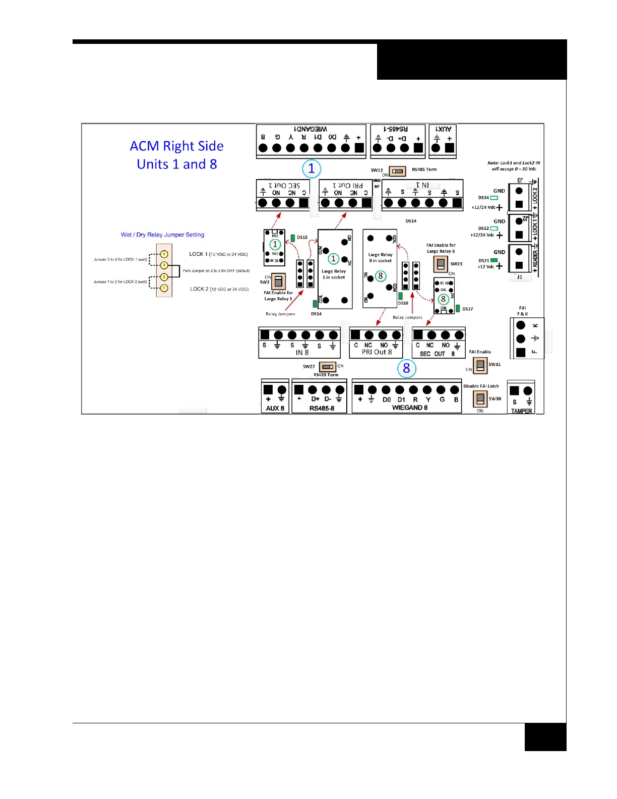
Figure 6. ACM Right Side- Sections 1 and 8
The various user visible controls, connectors and displays are shown. Sections
1 and 8 are indicated on most of the components. The jumper technique for wet
or dry relays is shown on the left.
The power connector labelled Reader is used for the reader and the logic.
The next 2 sets are not shown, but are identical to what is shown in Figure 6 on
page 21.