EasyManua.ls Logo

Software House iSTAR Ultra SE User Manual

Software House iSTAR Ultra SE
32 pages
To Next Page IconTo Next Page
Page #1 background imageLoading...
Page #1 background image
1
iSTAR Ultra SE Controller
Hardware Installation
Version D0
Part Number UM-311
October 2017
OVERVIEW
The iSTAR Ultra SE can be configured as an iSTAR Pro (in Pro Mode) or as an
iSTAR Ultra (in Ultra Mode for use with C•CURE 9000). The configuration is
based upon the GCM S1-4 switch setting.
The iSTAR Ultra consists of the following hardware components:
General Controller Module (GCM)
Access Control Module (ACM) - 2 maximum
or IP-ACM Ethernet Door Modules (supported in Ultra Mode only) - 32
maximum (IP-ACM installation and configuration is not included in this
document, see the IP-ACM Ethernet Door Module Quick Start Guide)
General Control
Module
The GCM is a General Purpose Module running the Linux
®
operating system.
The GCM provides the following features:
Two network Gigabit Ethernet ports.
An LCD panel that displays the current status, and provides built-in
diagnostics.
NOTE
The iSTAR Ultra SE in Pro Mode is supported by C•CURE 9000 and C•CURE 800/8000. Refer to
the iSTAR Pro Controller software configuration information when using the C•CURE 9000 or the
C•CURE 800/8000.
Pro Mode does not support the optional RC4 network encryption setting in either C•CURE 800 or
C•CURE 9000 systems. Check the Message Encryption system variable to ensure RC4 is not being
used.
The iSTAR Ultra SE in Ultra Mode is only supported on C•CURE 9000 v2.50 and higher. Refer
to the iSTAR Ultra Controller software configuration information when using the C•CURE 9000.
The iSTAR Ultra SE in Ultra Mode has a reduced feature set when compared to the iSTAR Ultra.
There are 16 Inputs instead of 24 and 8 Relays instead of 16, per ACM and no embedded lock
power management.
Question and Answer IconNeed help?

Do you have a question about the Software House iSTAR Ultra SE and is the answer not in the manual?

Software House iSTAR Ultra SE Specifications

General IconGeneral
ModeliSTAR Ultra SE
ConnectivityEthernet
Power Supply12-24 VDC
Inputs16 supervised inputs
Outputs8 relay outputs
Communication ProtocolTCP/IP
Operating Temperature0°C to 50°C
Humidity0 to 93% RH, non-condensing
Memory1 GB
Cardholder Capacity500, 000 cardholders
EnclosureMetal
ProcessorARM Cortex-A
Reader Interfaces8 reader ports
CertificationsUL294, CE

Summary

Overview of iSTAR Ultra SE Controller

General Control Module (GCM)

Describes the General Purpose Module running Linux OS with two network ports and an LCD.

Access Control Module (ACM)

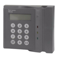
Provides interfaces for readers, inputs, and outputs for access control.

IP-ACM Ethernet Door Module

Manages access control for two readers via Ethernet.

iSTAR Ultra SE Requirements

Site Requirements

Ensures site readiness for installation, including certified installers and access control.

Wall Mount Dimensions and Environmental Requirements

Specifies physical dimensions for wall mounting and environmental operating conditions.

iSTAR Ultra SE Installation Guide

Wall Mount Installation Process

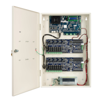
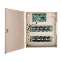
Detailed steps for mounting the iSTAR Ultra SE enclosure to a wall or uni-strut.

iSTAR Ultra SE Wall Mount Components

Wall Mount Door Components and Wiring

Details on door components and wiring for wall-mounted systems.

iSTAR Ultra SE Rack Mount Installation

Rack Mount Considerations and Grounding

Key considerations for rack mounting and essential grounding requirements.

iSTAR Ultra SE Power Specifications

GCM and ACM Power Requirements

Details electrical ratings and power input/output for GCM and ACM components.

iSTAR Ultra SE IP-ACM and Additional Power

IP-ACM Power Input/Output and AC Power

Specifies power requirements for IP-ACM and AC power configuration.

Additional Power Requirements and Safety

Covers external protection devices, circuit breakers, and electrical shock risks.

iSTAR Ultra SE Burglar Alarm and Battery

Burglar Alarm Installation Requirements

Specific requirements for burglar alarm installations, including power and standby.

GCM Battery and Pull-Tab Procedure

Details on the GCM's rechargeable battery and procedure for detaching the pull-tab.

iSTAR Ultra SE Wiring Specifications

Equipment Wiring Specs and Port Lengths

Table of wiring requirements, AWG, shield usage, and maximum lengths.

iSTAR Ultra SE Readers and Boards

UL Supported Readers and Accessory Boards

Lists readers and boards that are UL supported for various signaling methods.

iSTAR Ultra SE Part Numbers

System Component Part Numbers

Lists part numbers for main units, subassemblies, and adapter plates.

General Control Module (GCM) Components

GCM Processor, Switches, and Ports

Details on the processor module, DIP switches, rotary switch, and various ports.

GCM Network and Switch Functions

Network Ports and Reset Switch Operations

Information on Ethernet ports, soft reset (SW7), and hard processor reset (SW2).

GCM Rotary Switch and Encryption

SW3 Rotary Switch Functions

Descriptions of the 16-position rotary switch functions for diagnostics and settings.

Encryption S1-1 Configuration

Enables FIPS 197 AES 256-bit encryption for Ultra Mode.

GCM Configuration Modes and Connectors

Pro Mode, RS-485 Terminators, and USB

Settings for Pro Mode, RS-485 terminators, LCD contrast, and USB ports.

AC Fail and Low Battery Wiring

Details on wiring for AC Fail and Low Battery inputs.

GCM Input Signal Details

AC Fail and Low Battery Input Configuration

Describes the AC Fail and Low Battery inputs and their wiring requirements.

Tamper Input Wiring

Details wiring for the Tamper input (J1) connected to the enclosure.

iSTAR Ultra SE Visual Indicators

GCM Ports and Indicators (LEDs, LCD)

Information on GCM power, SD card, ports, and visual indicators like LEDs and LCD.

Access Control Module (ACM) Overview

ACM Functionality and Relay Details

Describes the ACM's function, reader ports, relays, and FAI capabilities.

ACM Inputs and Configuration

ACM Input Types and Supervision

Details on supervised inputs for Pro and Ultra modes and their configuration.

ACM Switches and Connectors

ACM Reset, RS-485 Terminators, Address

Covers ACM MCU reset, RS-485 terminators, and ACM address configuration.

ACM FAI Configuration and Ports

FAI Activation, Latching, and Connector Details

Configuration for FAI, USB connection, Tamper, and ACM Power inputs.

ACM FAI/Key and Wiegand Connections

FAI/Key Wiring and Wiegand Reader Connections

Details on wiring FAI/Key signals and direct Wiegand reader connections.

ACM Wiegand Port Details

Wiegand Port Pinouts and Ratings

Describes the pin configuration and electrical ratings for ACM Wiegand ports.

ACM Wiegand Port Controls and RS-485

LED/Beep Control and RS-485 Wiring

Configuration for Wiegand port LEDs/beeps and RS-485 reader wiring.

ACM Input Supervision Methods

ACM Input Supervision Wiring and Reporting

Explains input supervision wiring for Pro and Ultra modes, and reporting methods.

ACM LED Functions Summary

ACM LED Functions for Relays and RS-485

Summarizes LED functions for relays and RS-485 communication (Tx, Rx, Power).

iSTAR Ultra SE Initial Configuration

Static IP Address Configuration Steps

Procedure to configure the controller with a static IP address using ICU.

iSTAR Ultra SE IP Configuration Methods

DHCP IP Configuration and Utility Access

Steps for DHCP configuration and accessing the ICU and iSTAR Ultra Web utilities.

iSTAR Ultra SE Compliance Information

Standards and Regulatory Compliance

Lists relevant standards (UL, CSA, etc.) and Canadian radio emissions requirements.

Safety Ratings and Burglar Alarm Requirements

Details UL-294 ratings for Ultra/Pro Modes and burglar alarm specific requirements.

iSTAR Ultra SE Safety Information

FCC Compliance and General Safety Precautions

FCC Part 15 compliance for Class A devices and critical safety warnings.

Related product manuals