General Control Module
14
General Control Module
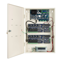
Figure 3. GCM Layout .
Network Connections
Connect a CAT 5, or better, RJ45 cable to either J5 or J6 (or both for
redundancy).
J5 Ethernet 1 Gbps
J6 Ethernet 1 Gbps
There are built in LEDs in the connectors that indicate the Ethernet Link and
Receive Data signals.
Switches
SW7 - Soft Reset (Reboot)
The SW7 push button saves all data in non-volatile memory and then reboots
the unit. It may take several minutes for the formatting and saving of the
data.The iSTAR Ultra is fully capable of operating without contact with the Host
after the reboot. (Use SW2 to reset the unit to factory default settings.)
SW2 - Hard Processor Reset
Note: SD Flash J14 and SW2 are
located on the back of the module.
SW2 resets the unit back to the factory default settings. Please contact
Technical Support before resetting back to the factory defaults.