Installation
6
6. Install the three lower mounting screws and the remaining top mounting
screw in between the two keyhole mounts.
7. Attach the conduit couplings to the knockout openings as needed to comply
with local code requirements.
8. Reattach the grounding wire between the door and the enclosure.
9. Secure the power inputs with zip-ties to maintain minimum safe distance for
electrical safety. Install in accordance with local and national regulations.
Non-limited power supply lines must maintain a minimum of 1/2” spacing
from limited power supply lines and other signaling lines.
10.When routing signal cables from the ACM to accessary boards on the door,
ensure that the cables are not pinched by the door and cables are routed in
accordance with NEC Codes or the applicable Local codes.
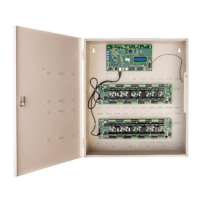
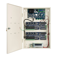
Wall Mount Door Components
The wall mounted iSTAR Ultra has stand-off’s on the enclosure door that can
support up to four RM Bus components.
The I/8, I/8-CSI, and R/8 boards are supported.
There can be any combination of the three boards including:
All I/8’s, all I/8-CSI’s or all R/8’s
Two I/8’s and two R/8’s
Three I/8’s and one R/8
Etc.
Wiring: Route the RM bus from each I/8 – R/8 board to the next. Connect the
end to one of the RM connectors on the ACM (i.e. J96, J83, J82, J10, J97, J98,
J99, or J100). See Figure 2 on page 7.