General Control Module
18
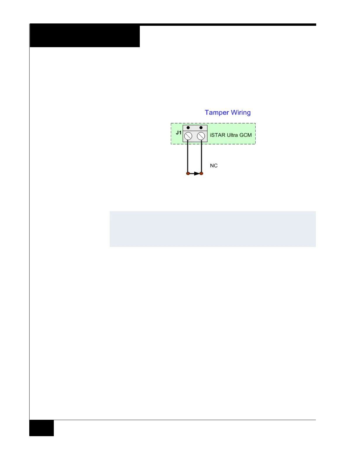
Tamper - J1
Figure 5 on page 18 shows Tamper - J1 NC (Normally Closed). It is connected
to the Tamper switch on the enclosure. If there is no standard enclosure, be
sure that there is a jumper across the two pins.
Figure 5. Tamper -J1
The tamper switch controls many LEDs, to preserve power and also turns off
the super bright LED when the door is open. When the door is opened the small
power LEDs are on. The LCD is also off when the door is closed.
GCM Power - J4
12 Vdc @ 4.5 Amps max (Note: pin 1 on the left is +12 Vdc, pin 2 is GND.)
J14 SD Card
Located on the back of the GCM to the left of the SOM, near the Hard Reset
switch. This non-volatile memory is where backups are stored.
The following ports are not to be used for connection for UL installations and
have not been evaluated by UL:
RS-485 1 and 2 (J26 and J27)
Each Port can support up to fifteen Hubs. Each Hub can support either one
Reader or eight Readers.
USB Micro Type AB - J7
Not supported. Future option.
RS-232 Diagnostic Port (P4)
Software Tech Support and Engineering use for troubleshooting.
NOTES
The Tamper, Low Battery, and AC power fail inputs must be enabled and
connected to report for compliance with UL requirements.
Shielded cable must be used for AC Fail and Low Battery Input
connections.