Access Control Module
27
Either Wiegand signaling or Magnetic signaling read heads are connected to
RM-4s or RM-4Es. The RM-4 or RM-4E readers are interfaced using RS-485 1
through RS-485-8. It is important that the ports are wired as shown in Ta bl e 9 .
The RS-485 connectors are not keyed so it is possible to reverse the signals. If
the ground connector (pin 4) is connected to +12 Vdc (pin 1), damage to the
power supply or the RM could result.
The reader number is determined by a hexadecimal switch on the RM, not by
the Port into which the reader is plugged.
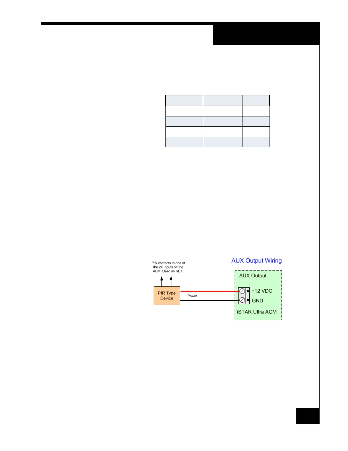
AUX Outputs
The AUX outputs can supply 1.5A for motion sensor or PIR type devices.
The voltage is 12 Vdc.
Figure 12. AUX Wiring
Wire the switch contacts of the PIR to one of the iSTAR Ultra inputs, using the
proper resistor supervision.
INPUTS
J13, J40, J42, J17, J44, J72, J68, J69
There are 24 onboard inputs, in sets of three, available on the ACM.The Input
supervision method is individually selected in the host.
Table 9. Pin Signals and Colors
STARx Pin Signal Color
1 +12 Vdc Red
2 Tx+ / Rx+ White
3 Tx- / Rx- Green
4 GND Black