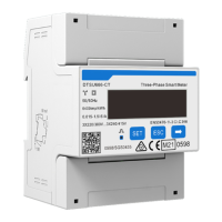
Cable Connection
6
Table 3-4 Cables for DTSU666-CT
Usage Terminal No.
Cable type
(Recommended)
Sectional
area
(mm
2
)
Outer
diameter
(mm)
Torque
(N·m)
Voltage
cable
2, 5, 8
Multi-core outdoor
copper wire
1.5~2.5 3~5
Max.: 0.4
Rec
.
:0.15~0.25
10
Max.: 1.7
Rec
.
:0.9~1.1
CT cable
1, 4, 7
Multi-core outdoor
copper wire
4~25 5~10
Max.: 1.7
Rec
.
:0.9~1.1
3, 6, 9
COM cable
24
Two-core outdoor
shielded twisted
pair cable
0.25~1.5 4~11
Max.: 0.4
Rec
.
:0.15~0.25
25
3.3 System Wiring
The following diagrams take the meter used in the PV system for example. For each meter
model, two communication methods are available. You can either connect the meter to
the inverter through communication cables, or through DataHub for centralized control.
The type and pin definition of inverter terminals for connecting meter and CT vary
depending on the inverter models. For specific pin information of the inverter, see the user
manual of the inverter and “Appendix”.
WARNING!
• Only the qualified personnel can perform the cable connection following local
standards and requirements.
• Before wiring, make sure you have cut off the power supply for the entire system.
NOTICE!
• DO NOT place the CT on the N wire.
• The CT must point away from the grid to the inverter or load.
• To prevent the CT from falling off, it is recommended to wrap the CT clip in circles
with insulating tape.
• When the system is powered on, ensure that the RS485 cables are kept separate from
the power cables to protect the inverter from potential damages.
• The wiring diagrams are for reference only. Actual wiring details depend on the on-
site conditions.

 Loading...