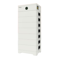
10
11
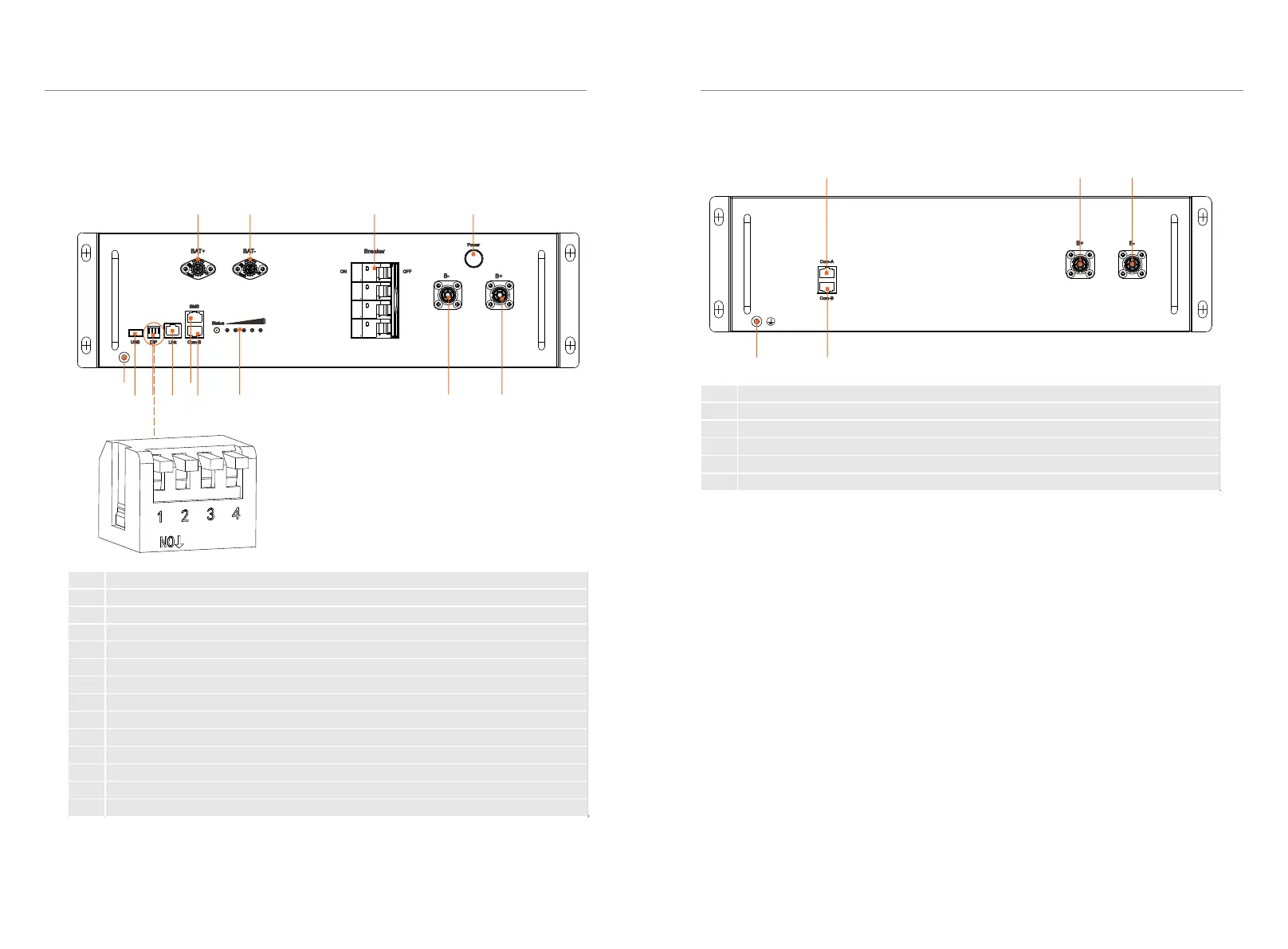
3.1.3 Appearance
■ Section view of TBMS-MCR0800
i ii iii
iv v
■ Section view of TP-HR25/TP-HR36
3. Product Introduction
3. Product Introduction
I II III IV
V IX
VI VII VIII X XI XII XIII
DIP switch 1: A reserved function
DIP switch 2: A reserved function
DIP switch 3: A reserved function
DIP switch 4: Terminal resistance
No. Description
I BAT+: Connect BMS's BAT+ to inverter's BAT+
II BAT-: Connect BMS's BAT - to inverter's BAT-
III Breaker: Input and output switch of battery module
IV Power Button: Open/close the battery system
V GND: BMS's GND
VI USB Port: A expansion function
VII DIP: Parallel operation of battery modules
VIII Link Port: Communication port for parallel operation of battery modules
IX BMS Port: Connect BMS's communication port and inverter's communication port
X COM-B: Connect battery module's COM A
XI Lamp Panel: Display real-time battery status
XII B-: Connect BMS‘s B- to battery module's B+
XIII B+: Connect BMS‘s B+ to battery module's B-
No. Description
i COM-A: Connect BMS's COM B or battery module's COM B
ii B+: Connect BMS's B- or battery module's B-
iii B-: Connect BMS's B+ or battery module's B+
iv GND: Battery module's GND
v COM-B: Connect battery module's COM A
 Loading...