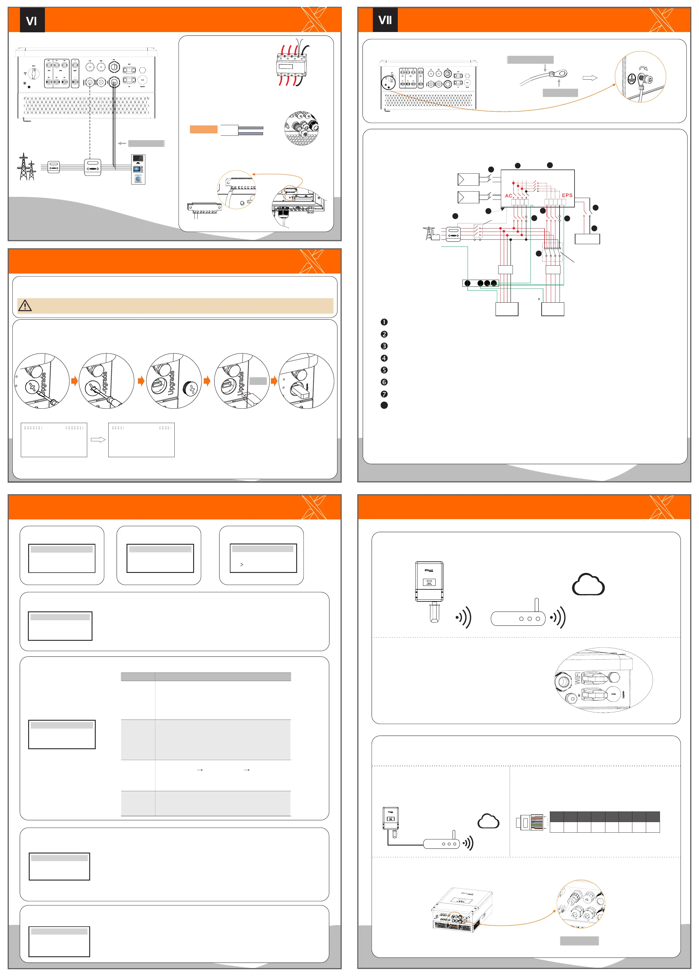
Earth Connection&Start Inverter
Earth Connection Steps(mandatory):
Turn on the DC switch at the bottom of the inverter to “ON” position.
Turn on the AC switch, EPS switch and battery switch.
Make sure the external EPS contactor is connected well. (if needed)
Make sure the battery is connected well.
Make sure the meter is connected well.
Make sure all the DC wirings and AC wirings are completed.
Ensure the inverter fixed well on the wall.
Startinverter
Inverter will start up automatically when the PV panels generate enough
energy or the battery is discharging.
Check the status of indicators and LCD screen. The left indicator should
be blue and the indicator screen should display the main interface.
Start Guide
Monitoring Operation
Cable size: 12AWG.
ring terminal
Meter Connection
English
Deutsch
Italian
Language
2017 ->06 <-06
10:19
Date time
Country
VDE0126
Safety
Mode Select
> self use <
Work Mode
> Mute: No
Frequency: 50Hz
EPS system
>Relay1 Setting
>Relay2 Setting
Finish
Relay Control
1.Set language 2.Set date time 3.Set the safety standard
This function allows the inverter able to control energy exported to the grid.
There are user value and factory value. The factory value is default which can not be charged
by user. The user value setting by installer must be less than the factory value.
4.Set export control
5.Set work mode
There are 4 work modes for choice.
Self use/ Back up mode/ Feed in Priority/ Force Time Use
6.Set EPS system(For E Version only)
X3-Hyrbid inverter with E Version can work on the EPS mode.
EPS parameters can be set as below.
- “Mute”means you can set the warning of system which has entered EPS mode.
- ”No”means there will be a buzzing and it is the default value.
- ”Yes”means you choose to shut down the warning function.
Besides ,if the buzzing is sharp, it means EPS output is over loads.“
Frequency “here can be set 50Hz or 60Hz please based on correlative loads.
7.Set relay control (The function is being developed)
Relay Control is an optional function which can control designated load
intelligently by consuming the surplus energy when feed in power reaches
certain value.
This function can only be achieved with solax product “Smart Plug”.
For specific operation, please refer to “ Smart Plug user manual”.
1) Insert L/N wires and the 485cable
into the meter.
Meter connection step
To grid-L
To inverter-L
To grid-N
To inverter-N
485A
485B
7 111
3
6 9
1516
4
3
1
4
7
11
6
9
Meter connection diagram
Electrical
grid
Home Electric meter,
Three phase
meter
Load
Meter connection
L
N
Communication interface bewteen inverter and meter is RS485 with
a RJ45 connector.
User value:
Export Control
4000W
Battery will stop discharing to keep higher capacity when the
grid is on. Only when the gird is off and PV energy is not
enough, battery will start to discharge to keep the emergency
load working normally.
This work mode applies to the area where suffering from
blackout regularly.
The priority of inverter output power is:
supplying the load feeding to the grid charging the
battery.
This work mode applies to the area with high feed-in tariff.
Self Use
(default)
Force Time Use
Back Up Mode
Feed in Priority
The PV generated power will be used to supply the local loads
firstly, then to charge the battery. The redundant power will
export to the public grid.
When there is no PV supplied, battery will discharge for local
loads firstly, and grid will supply power when the battery
capacity is not enough.
Parameter Comment
c. Insert the terminal into corresponding Meter terminal block
inside of the inverter.
a. Unscrew the cable nut of Meter connector and insert two
communication wires through it.
485A
485B
b. Trip the insulation from the communication cable, and then
insert it into a 8 pin green terminal.
wires
485A
485B
SolaX
meter
+
-
Battery
DPDT
E-BAR
Main switch
RCD
PV1+
PV1 -
PV2+
PV2 -
PE
SolaX X3-Hybrid inverter
Loads
L2
L1
L2L1 L3
N
L3
N
L1
L1
L2
L2
L3
L3
N
N PE
EPS
Loads
L2L1 L3
N
RCD
1
3
7
2
2
5
7
4
6
7
Firmware Upgrading
Please ensure the inverter is steadily powered on. Inverter must connect PV panels and keep the battery on through whole procedure of upgrading.
Please prepare an U-disk.
Preparation
Warning!
Make sure the PV input power is more than 180V (operate the upgrade on a sunny day), otherwise it may result in serious failing during upgrading.
1) Please contact our service support to get the update les, and extract itintoyourU-disk as following (Don’t modify the le name):
“update\ARM\618.00098.00_Hybrid_X3G3_Manager_VX.XX_XX-XX.usb”;
“update\DSP\618.00096.00_Hybrid_G3X3_Master_VX.XX_XX-XX.hex”;
>ARM
U-disk
Update
DSP
Update(ARM)
Updating---------25%
614.00365.00
Solax provides two ways for users to choose: Wifi(optinal) and Ethernet(LAN)
Inverter provides a Wifi port which can collect data from inverter and transmit it to monitoring-website via a Pocket WiFi.
(Purchase the product from supplier if needed)
Diagram
Could
Router
WiFi Connection Steps:
Step3. Create an user account online.( Please check the Pocket WiFi user
manual for more details.)
Step1. Plug Pocket Wifi into “WiFi” port at the bottom of the inverter.
Step2. Build the connection between the inverter and router.
Wifi(optinal)
LAN Connection Steps:
LAN Port
Communication interface bewteen inverter and router is RS485
with a RJ45 connector.
LAN PIN Definition
Application Occasion
This function is appliable for the below situation:
When the wifi signal is too weak to transmit data,user can
use LAN port for the monitoring with a data cable.
Note: The wifi module still needs to be connected
when using LAN connection.
TX+
TX-
RX+
X X
RX-
X X
1
2
3 4
5
6 7 8
1
8
Could
Router
data cable
Please refer to BMS connection steps (for user manual page32) for LAN connection. Please kindly noted the PIN definition and port
position will be slightly different.
Ethernet(LAN)
LAN communication is the standard communication interface. It can transmit the data between the router and inverter via the local
network.
2) Insertthe other side of the cable into the meter port on the
inverter.
Press the “Enter” key for five seconds to exit Off Mode. (The mode is factory
defaulted as Off Mode)
8
8
2) Press the “Enter” key for 5 seconds to enter Off Mode. Then unscrew the waterproof lid and insert U-disk into the “upgrade” port at the
bottom of the inverter.
3) The LCD will be shown as the picture. Then press up and down to select the one that you want to upgrade and press “OK” to confirm to
upgrade.
4) After the upgrade is finished, the LCD will display “succeed”(only for DSP upgrades), please remember to pull off the U-disk, screw the
waterproof lid and press the “Esc” to return to the Main interface. Then press the “Enter” key to exit Off Mode.
E
In this work mode there are two charge periods charging time
can be set flexibly, and it also allows to select whether charge
from the grid or not.
485A
485B

 Loading...


