Connection Steps
Grid Connection
Ø
X3-PRO G2 series inverter are designed for three phase grid. Rated grid voltage
is 230 V, frequency is 50/60 Hz. Other technical requests should comply with
the requirement of the local public grid.
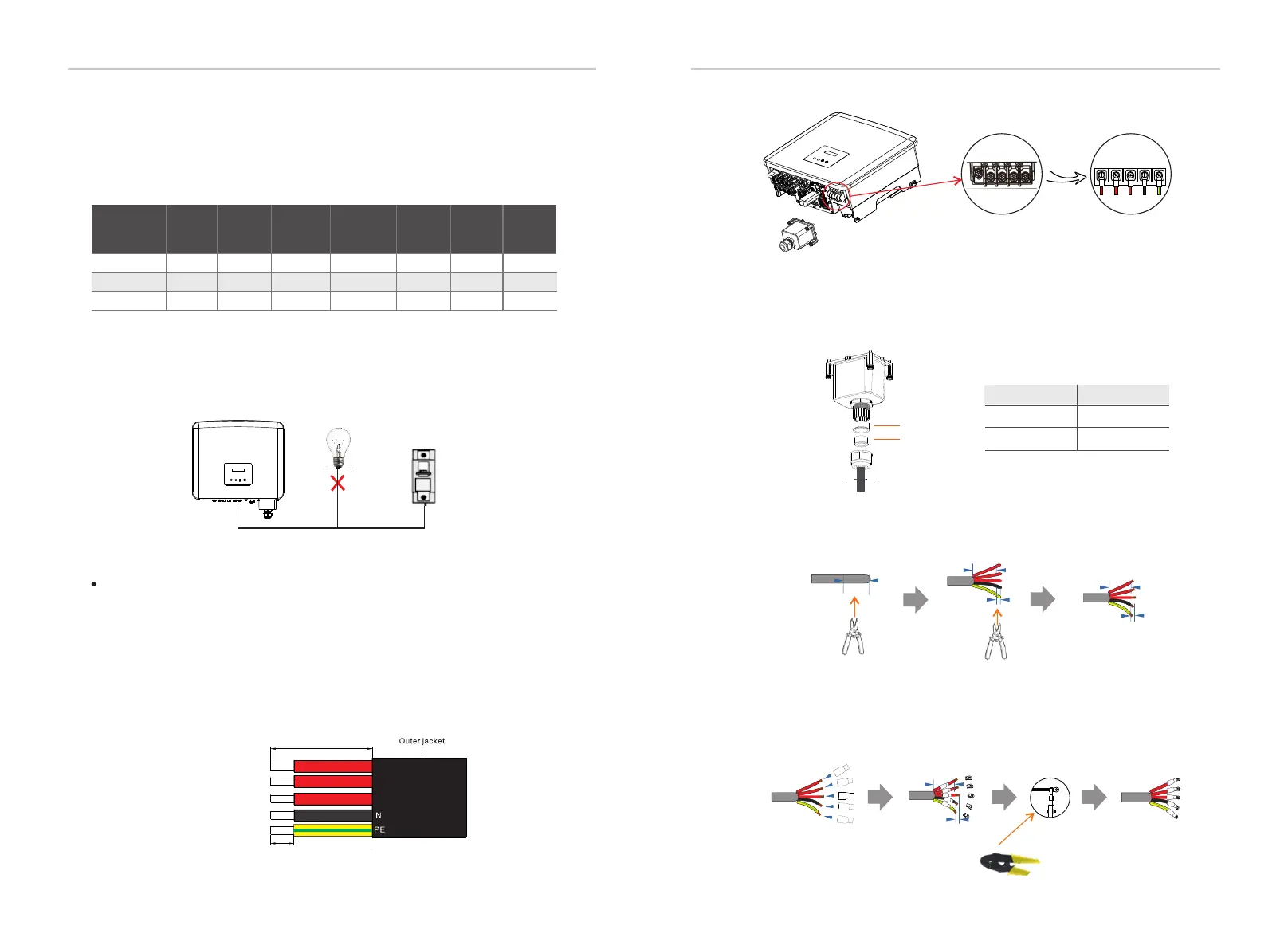
Micro-breaker should be installed between inverter and grid, any loads should
not be connected with inverter directly.
Note: Check the grid voltage and compare with the permissive voltage range
(refer to technical data).
a) Disconnect the circuit-bricker from all the phases and secure against re-
connection.
b) Select appropriate cable and prepare to strip the wires:
- Strip 82 mm of insulation from the cable end.
- Use the stripping pliers to strip 12 mm of insulation from wire ends as below.
Table 4 Cable and Micro-breaker recommended
Incorrect Connection between Load and Inverter
L1, L2, L3 Cable
PE, N Cable
4-5 mm²
Model
5-6 mm²
*The parameters have some differences because of different environment and material. Please
choose appropriate cable and micro-breaker according to the local conditions.
5-6 mm²
8-10 mm²
c) Fetch the AC waterproof cover from the carton.
e) Strip 82 mm of insulation from the cable ends by using the stripping
pliers.
Micro-breaker
16 A
32 A
50 A
2.5-5 mm²
3-6 mm²
3-6 mm²
3-6 mm²
X3-PRO-8K-G2(2D) X3-PRO-10K-G2(2D)
X3-PRO-15K-G2(2D)
X3-PRO-12K-G2(2D)
X3-PRO-30K-G2(3D) X3-PRO-25K-G2(3D)
20 A 25 A
3-6 mm²
3-6 mm²
6-8 mm²
5-6 mm²
40 A
10 mm²
63 A
3-6 mm²
28
29
L1 L2 L3
N PE
f ) Crimp the wire ends by using the wire crimper.
1
2 m
m
Stripping pliers
Stripping pliers
Crimp
8
2 m
m
7
0 mm
12 m
m
1
2 mm
7
0 m
m
7
0 mm
Wire crimper
g) Pull one terminal cover each over conductors L1, L2, L3, N and the
grounding conductor. The terminal cover must be below the stripped
conductor section.
h) Use the OT terminal crimping tool to press OT terminals.
Installation Installation
X3-PRO-17K-G2(2D)
X3-PRO-20K-G2(3D)
X3-PRO-20K-G2(2D)
X3-PRO-17K-G2(3D)
strip length
L1
L2
L3
82 m m
12 m m
d) Unscrew the fastening nut of the AC waterproof cover and remove the
sealing rings. Select appropriate number of the sealing rings according to
the outer diameter of the cable. Let the cable pass through the fastening
nut, the sealing ring(s) and the waterproof cover in sequence.
a
b
Diameter(mm)
Sealing ring(s)
a
a+b12~18
18~25
diameter
X3-PRO-15K-G2(3D)

 Loading...


