PV+
PV-
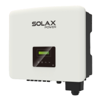
Step 5. Divide the PV terminal into 2 parts - the plug and the fastening
head. Insert the cable through the fastening head and the corresponding
plug. Note that the red and black lines correspond to different plugs.
Finally, force the cable pair into the plug, there will be a "click" sound,
which indicates that the connection is completed.
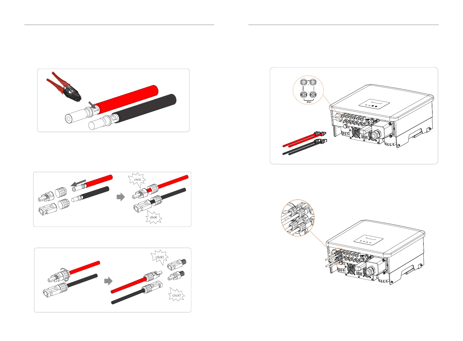
Step 6. Tighten the fastening head and insert into the corresponding
positive and negative (PV+/PV-) ports of the inverter.
Step 4. Tighten the PV pin contact and the wiring harness to make
the connection tight without looseness.
Crimping Tool
Negative
Positive
Positive
Negative
PV+
PV+
PV-
PV-
The following is the location of the inverter's positive and negative (PV+/PV-)
ports.
Schematic diagram of the inverter PV connected.
Installation Installation
26
27
 Loading...


