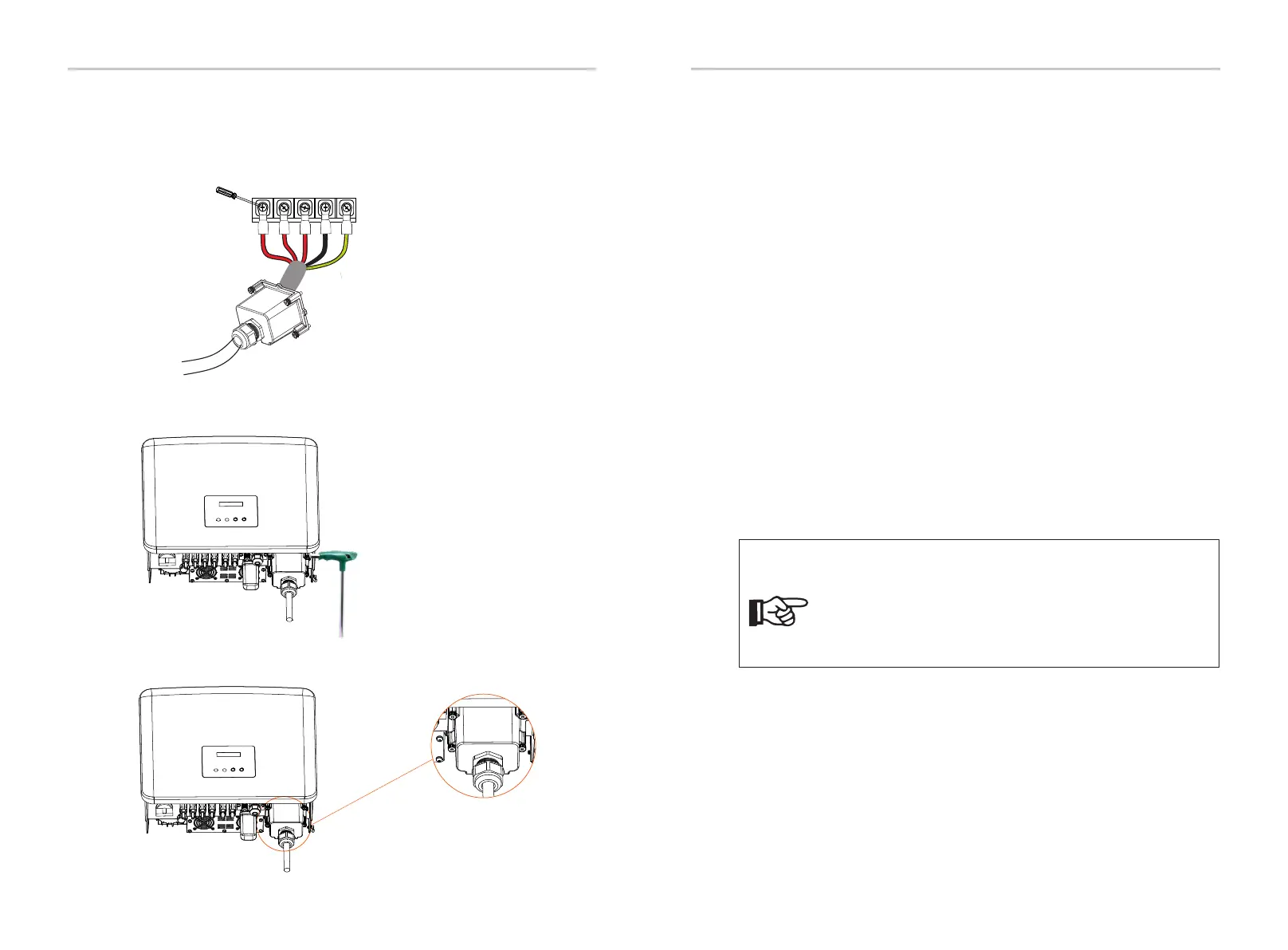
j) Align the waterproof cover and tighten the four screws with an inner
hexagonal wrench.
Torque: 1.2 0.1 ± N·m
Torque: 0.1 1.2± N·m
k) Tighten the waterproof fastening head.
Installation Installation
Mains cable (AC line cable) shall be short-circuit protected and thermal overload
protected.
Always fit the input cable with fuse. Normal gG (US:CC or T) fuses will protect the
input cable in short circuit situation. They will also prevent damage to adjoining
equipment.
Dimension the fuses according to local safety regulations, appropriate input
voltage and the related current of the solar inverter.
The rated short-circuit breaking capacity of the above protective device shall be
at least equal to the prospective fault current at the point of installation. See
section technical data of this manual for details.
2 2
AC output cable: Cu; L1,L2,L3, N+PE: 3*5.0 mm +2*5.0 mm for 8 kW and 3*6.0
mm +2*6.0 mm for kW/12 kW/15 kW and 3*8.0 mm +2*6.0 mm for 17 kW/20
2 2 2 2
10
2 2
kW and 3*10.0 mm +2*6.0 mm for 25 kW/30 kW @40 ambient temperature ℃
with a max length of 5 m, with operating time of the fuses is less than 5 seconds,
installation method B2 according to 60204-1:2006, annex D: cable in conduit EN
cable trunking system, number of loaded circuit only one. Use H07 (cord RNF
designation 60245 66) for an ambient temperature of 40℃ or less and use IEC
90℃ wire for ambient temperature between 40℃ and 60℃.
Selection of Fuses and Cables
30
31
L1 L2 L3 N PE
i) Tighten the screws of the wire ends with a screwdriver.
1. For condition differing from those mentioned above,
dimension the cables according to local safety regulations,
appropriate input voltage and the load current of the unit.
(You can choose a thicker cable but the fuses must be rated
according to the rating of the cable.)
2. Fuses must be approved by Notified Body.
Note!
Therefore the current-carrying capacity of the components and sub-assemblies
provided in the end-use system (connectors, cables, junction box, switchgear,
etc.) and the reverse current PV modules shall be considered based on the
feedback current and reverse current. The direct current (DC) circuit breaker or
fuse between each solar generator and inverter shall be provided based on
solar inverter input ratings.
Select DC cables based on the above inverter back-feed current and ISC PV
rating and Vmax ratings.
 Loading...


