9
1. Attach the Upright Tubes (4 & 5) onto the Frame Base (2) with eight Button
Head Socket Bolts (130) by using the Combination M5 Allen Wrench & Phil-
lips Head Screw Driver (131). Do not tighten the bolts completely until
ASSEMBLY STEP 3
3
HARDWARE STEP 3
#130. 5/16”x 1/2” Button
Head Socket Bolts (8 pcs)
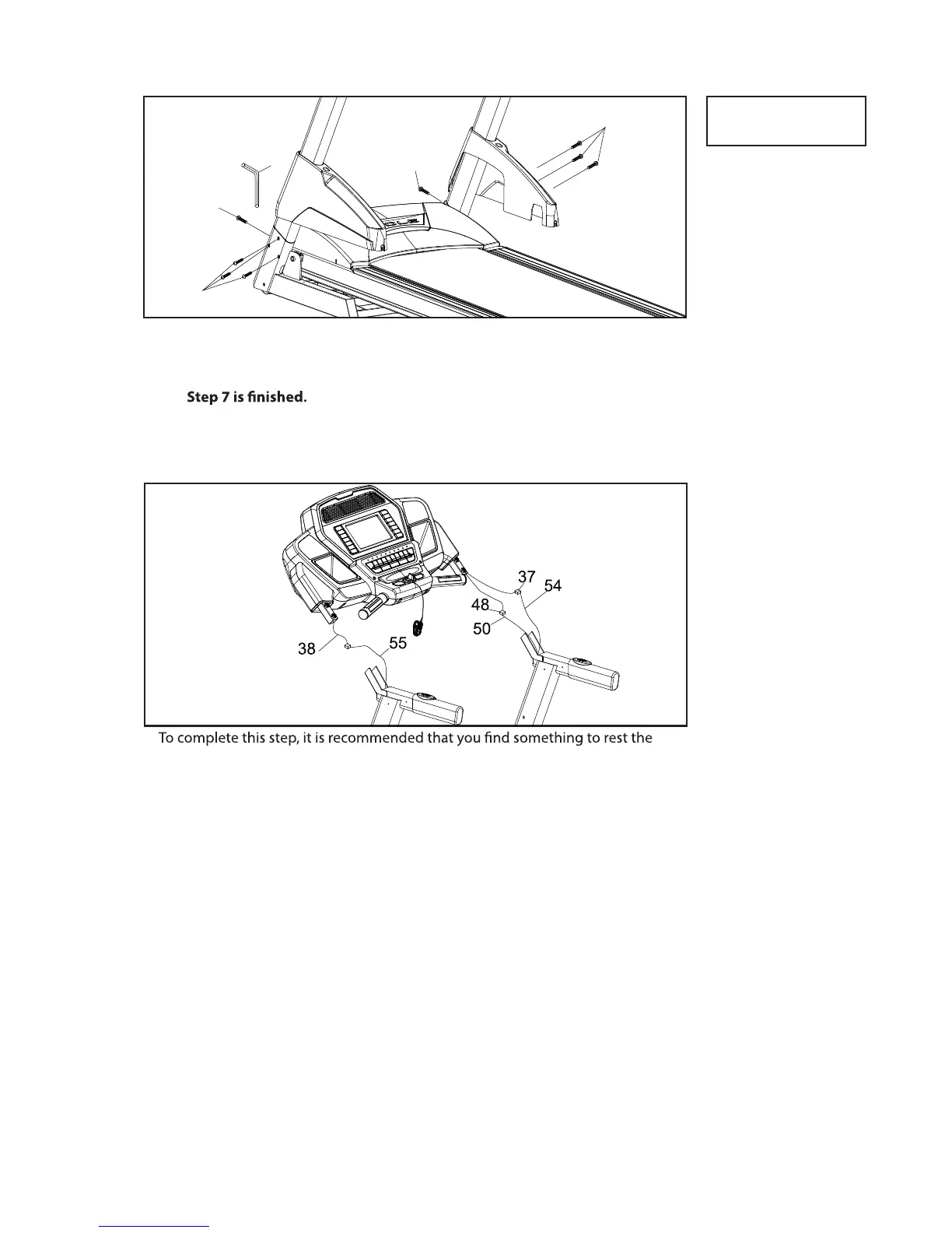
1. Connect the Speed Adjustment Switch Cable (54) to the Speed Cable, Upper
(37) Connect the Incline Adjustment Switch Cable (55) to the Incline Cable,
Upper (38). Connect the Computer Cable, Middle (50) and Computer Cable,
Upper (48). Tuck the excess cable into the hand rail tubing to prevent it from
getting pinched.
ASSEMBLY STEP 4
4
console on at the appropriate height or have someone hold the console while
you connect the cables
Before attaching the hardware to Step 5, make sure the cables you just connected don’t
get pinched in between the steel tubing. If they do, this may cause issues that prevent
the treadmill from operating properly.
F80 / F83 / F85 TREADMILL