11
1. Attach the Support tube (15) between the upright tubes (4 & 5) with four
Button Head Socket Bolts (151 mly.
2. Place the Beverage Holder (150) on top of the Support tube (15) as shown in
the illustration.
3. Place the magnet of the safety key (75) in between the Start and Stop
buttons (if it isn’t already attached). The treadmill will not function without this
in place.
4. Check to make sure all bolts and screws are completely tightened.
ASSEMBLY STEP 7
7
HARDWARE STEP 7
#151. 5/16”x3/4”
Button Head Socket
Bolts (4 pcs)
#75. Safety Key
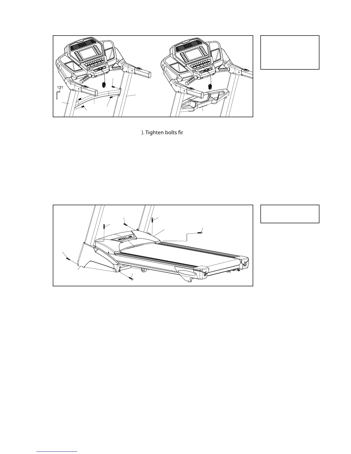
1. Attach the Console mast covers (62 & 63) to the Frame Base (2) with six
Tapping Screws (120). Tighten screws using the Combination M5 Allen
Wrench & Phillips Head Screw Driver (131).
ASSEMBLY STEP 8
8
HARDWARE STEP 8
#120. 5x16mm
Tapping Screws (6 pcs)
F80 / F83 / F85 TREADMILL