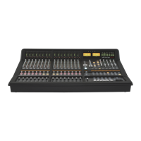
Do you have a question about the Solid State Logic Live L100 and is the answer not in the manual?
Setting up clocking for Live consoles and stageboxes.
Understanding internal and external clock sources for a Live system.
How to select the system clock source via the console menu.
Setting up clock synchronization for Dante networks.
Configuring the console to sync to the Dante network master.
Configuring console to sync to Dante network master via bridge.
Default clocking and sync options for MADI stageboxes.
Using AES/EBU connections with sample rate converters.
Table of sample rate capabilities for AES/EBU connections.
Detailed labels for front panel connectors on the L100 console.
Detailed labels for rear panel connectors on the L100 console.
Top-down diagram showing L100 console dimensions.
Side view diagram showing L100 console dimensions.
Detailed labels for front panel connectors on the L200 console.
Detailed labels for rear panel connectors on the L200 console.
Top-down diagram showing L200 console dimensions.
Side view diagram showing L200 console dimensions.
Detailed labels for front panel connectors on L300/L350 consoles.
Detailed labels for rear panel connectors on L300/L350 consoles.
Top-down diagram showing L300/L350 console dimensions.
Side view diagram showing L300/L350 console dimensions.
Detailed labels for front panel connectors on the L500 Plus console.
Detailed labels for rear panel connectors on the L500 Plus console.
Top-down diagram showing L500 Plus console dimensions.
Side view diagram showing L500 Plus console dimensions.
Detailed labels for front panel connectors on the L550 console.
Detailed labels for rear panel connectors on the L550 console.
Top-down diagram showing L550 console dimensions.
Side view diagram showing L550 console dimensions.
Labels for rear connections on the Remote Tile.
Physical specifications for the Remote Tile.
Labels for front panel connections on the ML 32.32 stagebox.
Labels for rear panel connections on the ML 32.32 stagebox.
Description of the ML 0.32 Output Stagebox.
Physical specifications for the ML 32.32 Stagebox.
Physical specifications for the D 32.32 AES Stagebox.
Physical specifications for the BLII.D Concentrator.
Physical specifications for the BLII Bridge.
Physical specifications for the X-Light Bridge.
Details for the IEC 60320 - C13 power connector.
Co-axial MADI connections and cable requirements.
Blacklight II fibre connections (opticalCON DUO).
AES/EBU XLR connector pinout and cable details.
Fibre MADI connection for external effects processors.
USB 2.0 specifications for peripherals.
USB power connection for devices.
USB B connection for console interface.
MIDI connections for stagebox control.
AES11 DARS input/output connector details.
Linear Time Code (LTC) connections via XLR.
GPIO connections for stageboxes.
Explanation of MADI setup controls and LEDs.
Explanation of the CLOCK button function for stageboxes.
Dante SFP cage details.
X-Light fibre connection details.
Diagram of a basic L500 Plus single system setup.
Specifications for stands for L500 series consoles.
| Sample Rate | 96 kHz |
|---|---|
| Bit Depth | 24-bit |
| EQ | 4-band parametric |
| Dynamics | Compressor, Gate |
| Connectivity | Ethernet, USB |
| Effects | Built-in |
| I/O | 32x32 |
| Screen | Touchscreen |
| Outputs | 16 |
| Automation | Full |
| Power Supply | Internal |
