EasyManuals Logo

Solid State Logic Live L550 User Manual

Solid State Logic Live L550
43 pages
To Next Page IconTo Next Page
To Previous Page IconTo Previous Page
Page #35 background imageLoading...
Page #35 background image
SSL Live Installation Information
GP Output - D-type Female
Pin
Description
Pin
Description
1
Output 1A
7
Output 7A
14
Output 1B
20
Output 7B
2
Output 2A
8
Output 8A
15
Output 2B
21
Output 8B
3
Output 3A
9
Output 9A
16
Output 3B
22
Output 9B
4
Output 4A
10
Output 10A
17
Output 4B
23
Output 10B
5
Output 5A
11
Output 11A
18
Output 5B
24
Output 11B
6
Output 6A
12
Output 12A
19
Output 6B
25
Output 12B
13
+12V (450mA max)
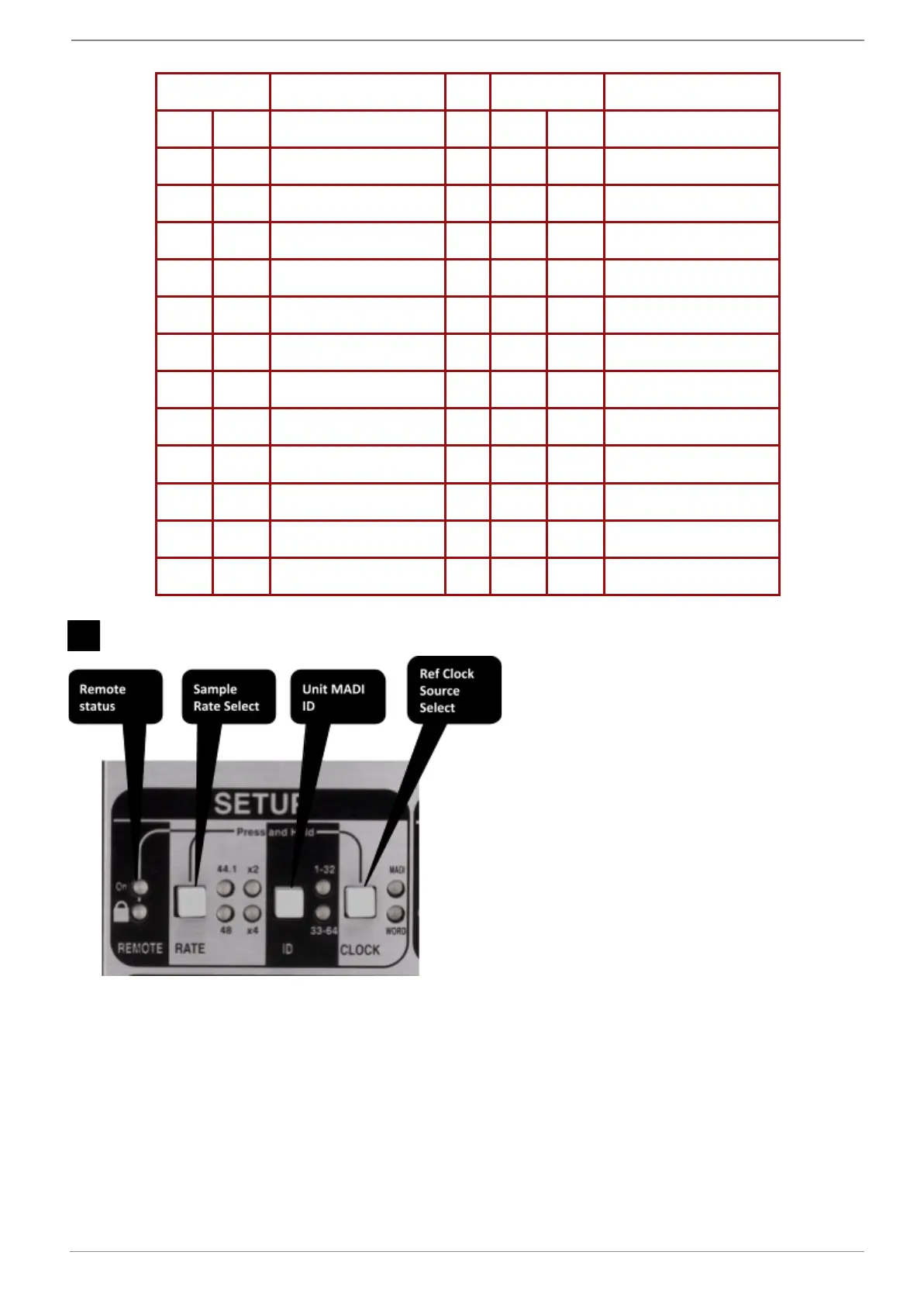
*20 - Setup Controls: MADI
REMOTE - Padlock LED
Red indicates SETUP controls are locked
Press and hold RATE & CLOCK simultaneously to activate controls. The Padlock LED will flash green
to indicate controls are unlocked. After a few moments of inactivity, the controls will lock again.
REMOTE - On LED
On LED flashes green when remote MADI control data is received.
RATE - Sample Rate
RATE button selects different box sample rates (See Live Console Synchronisation & Clocking earlier
in this guide)
www.solidstatelogic.com Page 35 of 43

Table of Contents

Questions and Answers:

Question and Answer IconNeed help?

Do you have a question about the Solid State Logic Live L550 and is the answer not in the manual?

Solid State Logic Live L550 Specifications

General IconGeneral
BrandSolid State Logic
ModelLive L550
CategoryMusic Mixer
LanguageEnglish

Related product manuals