Solidremote 202U 2-Channel Stand Alone Receiver Instructions
Visit solidremote.help if you need help
ALWAYS post a new topic in forum & double check email for prompt response, thanks.
--- Page
1
Thank you for purchasing Solidremote 202U 2-channel stand alone
receiver. Familiarise yourself with the following instructions prior to
commencing set up. Store this information in a safe place for future
reference.
Short Introduction
202U receiver has two relays on board which provide normally open
& normally closed voltage-free dry contact (doesn’t output power)
for controlling virtually any electronic device. In default standard
mode, both relays can be set to any of three modes – pulse
(momentary), hold (toggle) or interlock latching using DIP switches.
Setting Relay Operation in Standard Mode
Pulse / Momentary – Relay contact is active whilst transmitter
button is pressed, min. active period is ~0.5s
Hold / Toggle – Relay changes state at each press of transmtter
button. Hold, Release, Hold etc. (like an on/off switch)
Interlock Latching – Two relays interact with each other, Relay 1 on
then Relay 2 off, Relay 2 on then Relay 1 off. (useful in small DC
motor reverse polarity control)
DIP Switch 1 ON ON OFF OFF
DIP Switch 2 ON OFF ON OFF
↓
with DIP Switch 3 OFF
Relay 1 Pulse Hold Pulse
Relay 2 Hold Hold
Interlock
Latching
Pulse
To turn off both relays in this mode, press the special function
button which is assigned to both relays 1&2 (programmed by press
both PRG1 & PRG2 when storing transmitter code).
Storing Transmitter Code
1. Press and hold PRG1 (for Relay 1) or PRG2 (for Relay 2) or
PRG1 and PRG2 (for both Relay 1 & 2) until SIG LED turned on.
2. Press the transmitter button you would like to control the channel
once until SIG LED flashes, then release transmitter button.
3. The SIG LED will flash quickly three times, indicating that the
code has been stored.
4. Release all PRG button on receiver.
5. Press the programmed transmitter button to test operation.
Remove Single Transmitter Code: Repeat steps 1-5 above. During
removal process, SIG LED on step 3 will flash slowly three times
(instead of quickly), indicating that the code has been removed.
Deleting All Stored Transmitter Codes
1. Turn power off to receiver.
2. Press and hold both PRG1 and PRG2 button.
3. While holding both PRG1 and PRG2 - turn power on again. After
5 seconds the SIG LED will illuminate to indicate receivers memory
has been cleared.
4. Release PRG1 and PRG2. All the stored codes should now be
deleted. Confirm this by pressing transmitters previously used to
operate the device. There should be no response.
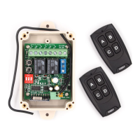
Receiver Function Diagram
Terminal
Learn Button
Mode Select
Signal LED Power LED
Limit Switch
Relay LED
MCU
Receiver Module
Power
Supply
2 x Relay
Technical Specifications
Power Supply: 9V-24V AC or 9V-30V DC
Frequency: 433.92MHz OOK
Memory Capacity: 510 Transmitters (up to 14 buttons each)
Antenna Impedance: 50 Ohms (RG58)
✔ Relay Contact Rating:
Resistive Load (cosΦ=1): 10A @ 14V DC or 10A @ 120V AC
Inductive Load
(cosΦ=0.4 L/R=7msec): 6A @ 14VDC
Temperature Rating: -4°F to 131°F (-20°C to 55°C)
Weight: 0.25 lbs. (0.11kg)
Physical Size: 4.33"L x 2.36"W x 1.37"H (11cmL x 6cmW x 3.5cmH)