Preparing the equipment for use
ENGLISH 11
6.2 Assembly - vacuum operation – only
model 441 (with model 440 as
accessory)
Fit the following parts for the vacuum operation:
Exhaust air elbow (20) to be fitted to the standard
machine.
Catcher (21) to be fitted to the exhaust air elbow.
Vacuum pipe (19) to be fitted to the standard
machine.
[Note: When preparing model 440 with vacuum
operation accessory kit 49 00 546 for the first time,
also fit the anti-static wire in accordance with the
details supplied with the accessory kit. For model
441, the anti-static wire is already fitted as standard.]
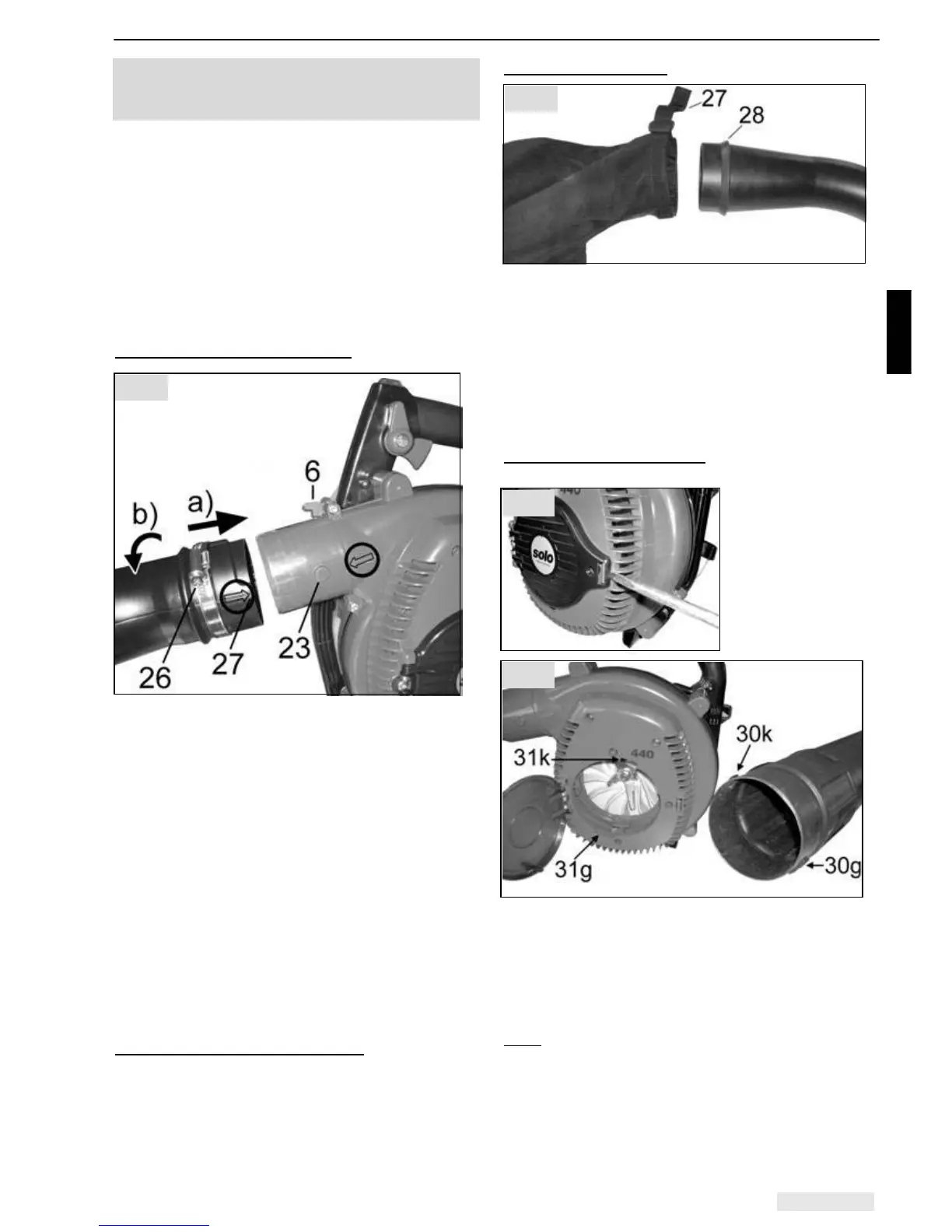
Exhaust air elbow assembly (20)
Tip: To make the assembly easier, the standard
machine can be positioned on a level surface, air
filter side down. For this, ensure that the tank cap is
tightly secured to prevent fuel spillage.
• Undo clip (26) on exhaust air elbow (20).
a) Push exhaust air elbow (20) with groove (27) over
cam (23) of the standard machine.
The arrows on the exhaust air elbow and the
standard machine must be aligned accurately,
when the parts are pushed together (the wide
groove (27) over the large cam (23), and the
narrow groove over the smaller cam).
b) Rotate the exhaust air elbow through 45º over the
stand until the lock (6) engages behind the groove
on the exhaust air elbow; do not tighten
excessively!
• Secure clip (26).
Dismantling the exhaust air elbow
• Undo clip (26).
• Gently lift up the lock (6) and rotate the exhaust
air elbow back at the same time until the arrows
are exactly lined up again.
• Pull the exhaust air elbow from the standard
equipment.
Catcher assembly (21)
• Open Velcro strap (27) on catcher.
• Push the catcher so far over the elbow, that the
entire width of the Velcro strip is located behind
the bead (28) on the reducing part of the elbow.
• Tighten and close the Velcro strip.
• Secure the shoulder strap to the catcher eyes.
To dismantle the catcher, open the Velcro strip and
remove the catcher from the exhaust air elbow.
Vacuum pipe assembly (19)
With a screwdriver,
push into the side
opening of the fan
cover to release it.
Open the fan cover wide. Push vacuum pipe cams
(30) into grooves (31) on the inner ring of the fan
casing. Ensure that the large cam (30g) is located in
the wide groove (31g) and the small cam (30k) in the
narrow groove (31k).
Rotate the vacuum pipe clockwise until it is clearly felt
to engage.
Note:
To enable the power tool which has been
attached for vacuum operation to be stored on stand
(14) again Î
first loosen the clip (26) and lift up the lock (6), then
rotate the exhaust air elbow back so that the arrows
on the exhaust air elbow and the standard unit are
exactly lined up again.
Fig. 7
Fig. 8
Fig. 6
Fig. 9