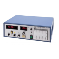
3.8 CHANNEL 1-4 EEG AMPLIFIER GAIN TEST
Connect an oscillator through an 80db divider into the electrode inputs of the channel 1-4
amplifier according to fig. 3.7. Make sure the gain of the amplifiers is set at 200µv/cm.
Adjust output of oscillator to 10 Hz and 2.0 volts p-p sinewave. Turn on
THYMATRON®IV and note the EEG output should be 1 cm p-p sinewave on the
printout. Check for 3db points by setting frequency to 1 Hz and then to 25 Hz and note 3
db drop in amplitude.
fig. 3.7
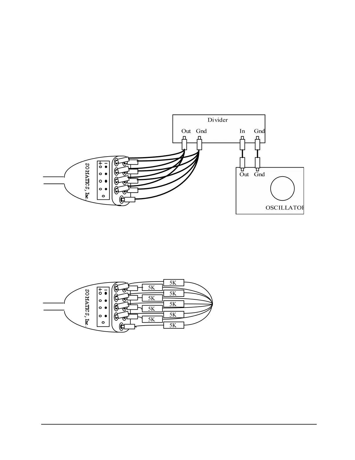
3.9 EEG AMPLIFIER NOISE TEST
Connect three 5K_ resistors into the electrode input of the EEG amplifier according to fig.
3.8. With the oscilloscope connected to the EEG output jack, note that output noise is no
more than 50 mv (equivalent to 5µv at the input).
fig. 3.8
3.10 EEG AMPLIFIER SOUND TEST
With oscillator and oscilloscope connected, connect dummy load to the ECT output. Turn
THYMATRON®IV on and press TREAT button. Right after the stimulus is delivered a
modulated sound should be heard from the speaker. The volume knob on the back may be
adjusted. Vary the frequency and amplitude of the oscillator and note the changes in the
sound.