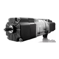
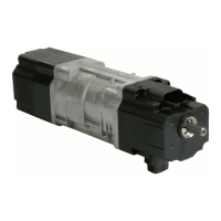
Short installation guide
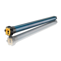
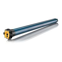
J4 drive for External Venitian Blinds
Common (L)
3 Down Brown
2 Up Black
Neutral (N) 1 Blue
Earth (
)
Green-Yellow
1 2 3
Drive connector
EN
J4 WT
These instructions apply to all
J4WT drive, the different versions
of which are available in the current
catalogue.
FIELD OF APPLICATION
J4 drive are designed to drive all
types of tiltable venetian blinds.
The installer, who must be a
motorisation and home automation
professional, must ensure that the
motorised product is installed in
accordance with the standards in
force in the country in which it is
installed such as EN 13561 relating
to outdoor screens and awnings.
LIABILITY
Please read these instructions
carefully before installing and using
the drive. In addition to following the
instructions given in this guide, the
instructions detailed in the attached
Safety instructions document
must also be observed.
The drive must be installed by a
motorisation and home automation
professional, according to
instructions from Somfy and the
regulations applicable in the country
in which it is commissioned.
It is prohibited to use the drive
outside the field of application
described above. Such use, and
any failure to comply with the
instructions given in this guide and
in the attached Safety instructions
document, absolves Somfy of
any liability and invalidates the
warranty.
The installer must inform its
customers of the operating and
maintenance conditions for the
drive and must provide them
with the instructions for use and
maintenance, and the attached
Safety instructions document,
aer installing the drive. Any
Aer-Sales Service operation on
the drive must be performed by a
motorisation and home automation
professional.
If in doubt when installing the drive,
or to obtain additional information,
contact a Somfy adviser or go to the
website www.somfy.com.
GENARAL SAFETY
INSTRUCTIONS
The installation must be protected
from all unauthorised use.
Comply with the assembly and
operating guides, in particular
the safety instructions of the
manufacturer of the device to be
used.
To remove the drive supply cable
: Please use the J4 cable removal
tool supplied, ref: 9017811.
The drive, torque and operating
time must be adjusted accroding to
the whole installation.
The moving parts of the drives must
be protected if operating below
2.50 m from ground level.
Disconnect all connected cables
from the power supply before
working on the installation.
SAFETY INSTRUCTIONS FOR
WIRING
Cables which pass through a
metal wall must be protected
and isolated using a sheath or
sleeve.
Attach cables to prevent any
contact with moving parts.
If the drive is used outdoors,
and if the power supply cable is
a type H05-VVF cable, the cable
should be installed in a UV-resistant
duct, e.g. under a gland.
Leave the drive power supply
cable accessible: it must be
possible to replace it easily.
Always make a loop in the
power supply cable to prevent
water entering the drive.
SPECIFIC INSTRUCTIONS
Do not connect the drive to an
isolating transformer.
Do not use mains disconnection
devices in conjunction with a drive.
Use only mechanical switches
or electro-mechanical switches
(ex : relays) to control drives. The
contacts of the relays must not be
bypassed by capacitors.
In user mode, do not use electric
switches allowing simultaneous ▲
and ▼ contact.
The drive must not be driven by a
solid-state relay or triac relay.
Always refer to the control system
instructions to do the proper wiring.
For control systems using
an «automatic running time
recognition procedure», please
consider the recommendations
given by the producer of the
controller : the N wire of the
controller has to be connected to
the N wire of each drive.
Continuous orders of at least
180ms must be sent to the drive to
ensure a proper execution.
Intervals between “Down” and “Up”
orders must be at least 500ms.
The drive can be wired in parallel.
In this case take in consideration
the maximal load of the switch/
controller used (starting current
peak of the drive : 9 A in the first
3ms).
Phases and neutrals of each drive
must be connected together
respectively as shown below :
Common (down)
Common (up)
Neutral
Earth
M MM
Ref. 5133932A
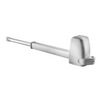
THE WT SETTING TOOL
You can choose to use the WT setting tool or a control
point, type non-locking double pushbutton. Their
actions are equivalent, as below:
The type «non-locking double pushbutton» is only
useful for installation steps.
GUIDE TO FOLLOW
This short installation guide allows you to
follow step by step the drive installation
key stages.
Further information about the installation
of this drive is also available online:
LEXICON
Safety warning!
Caution!
Information
Control point, type non-locking
double pushbutton
▲
«Up» button /
▼
«Down» button
WT setting tool
Ref. Europe : 9015971
Ref. Switzerland : 9016772
▼▲
WT button of the WT setting tool
Mushroom
Images are not contractually binding.
Translated instructions
M
L
N
2
1
3
Drive
2 - Instructions to be respected 1 - Advance information3 - Wiring
www.somfy.info
1/2
5133932A_J4_WT-EN.indd 1 06/10/2017 09:49:53