Commissioning
General information
• DIP switches set to "OFF" position on delivery.
• Do not apply external voltage to the connections of the control system,
otherwise the control system is immediately destroyed.
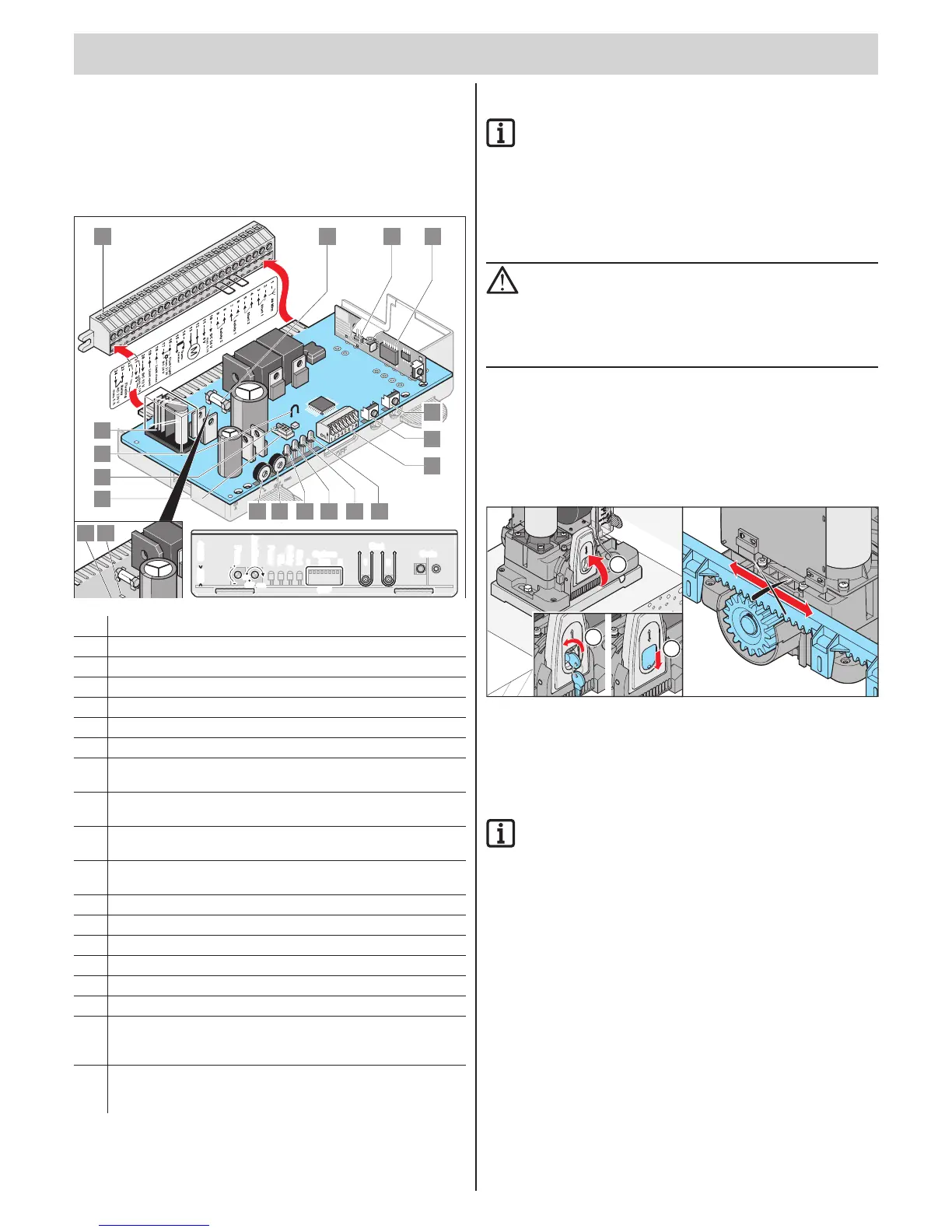
Overview of the control system
24
23
22
21
20
19 18
17
16
15 14
13
12
10
9
8
7
6
5 4
3
2
1
11
LE
D
1 L E D
2
LE
D
3 LE
D
4
T
1
P
2
T2
1
2
5
6
7
14
15
16
17
43
19 18
9810111213
Start
Code
1
1 8ON
OFF
OFF
max.
ON
Options
41035
Force
TimeAuto
Safety
Start
Power
WL
ABS
2
Start
Code
1
18ON
OFF
OFF
max.
ON
Options
41035
Force
TimeAuto
Safety
Start
Power
WL
ABS
2
1. Direct connector, 24-pole
2. Fuse for warning light-1 connection, terminal 16 + 17
3. Connection of the external antenna
4. Radio receiver
5. Button 2 (T2*)
6. Button 1 (T1*)
7. DIP switch 1 - 8
8. Start (LED 4*)
Lights when a radio command is sent or a button is pressed.
9. Safety (LED 3*)
Lights when a safety input is actuated.
10. WL (LED 2*)
Flashes when the operator opens or closes the gate.
11. Power (LED 1*)
Lights when mains power is on.
12. Potentiometer (P2*) for setting time of automatic closing
13. Potentiometer (P1*) for adjusting the power tolerance.
14. Connection of TorMinal
15. Protection against incorrect insertion for the connection of TorMinal
16. Wire jumper, disconnecting switches off soft running.
17. Relay contact, Terminals 23 + 24
18. LED:
Operator left: end position gate CLOSED
Operator right: Door end position OPEN
19. LED:
Operator left: Door end position OPEN
Operator right: Door end position CLOSED
* See the controller pcb for this label.
Safety instructions
IMPORTANT INFORMATION!
After installation of the operator the person responsible for
installation of the drive must issue an EC Declaration of
Conformity for the gate system in accordance with Machinery
Directive 2006/42/EC and attach the CE symbol and a type
plate. This is also required for private installations and also
if the operator is retrofitted to a manually operated gate.
This documentation and the Installation and Operating
Instructions are retained by the operator.
ATTENTION!
The adjustment of the force tolerance is safety-relevant and
must be performed by qualified personnel with the utmost care.
If the adjustment of the spring unit is excessively high,
people or animals could be injured and objects damaged.
Select a force tolerance that is as low as possible so that
obstacles are detected quickly and safely.
Programming the operator
The control unit has an automatic force setting. The control system
memorizes the required force during the "OPEN" and "CLOSE" gate
movements and stores it when the end position has been reached.
Locking the operator
1
2
3
1. Traverse operator to centre position.
2. Lift lever (1) up and lock with key until the motor locks - loud click.
Release lever (1).
3. Remove key and push dust cap down.
IMPORTANT INFORMATION!
Move gate back and forth by hand so the pinion meshes with
the rack more easily and the motor can lock.
⇒ Operator is locked and the gate can only be moved with the motor
4. Plug in controller.
5. Switch on main switch.
⇒ LED (power) on
 Loading...