6
SONAMP DSP 2-150 MULTI-CHANNEL POWER AMPLIFIER INSTRUCTION MANUAL
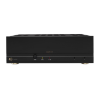
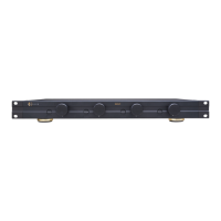
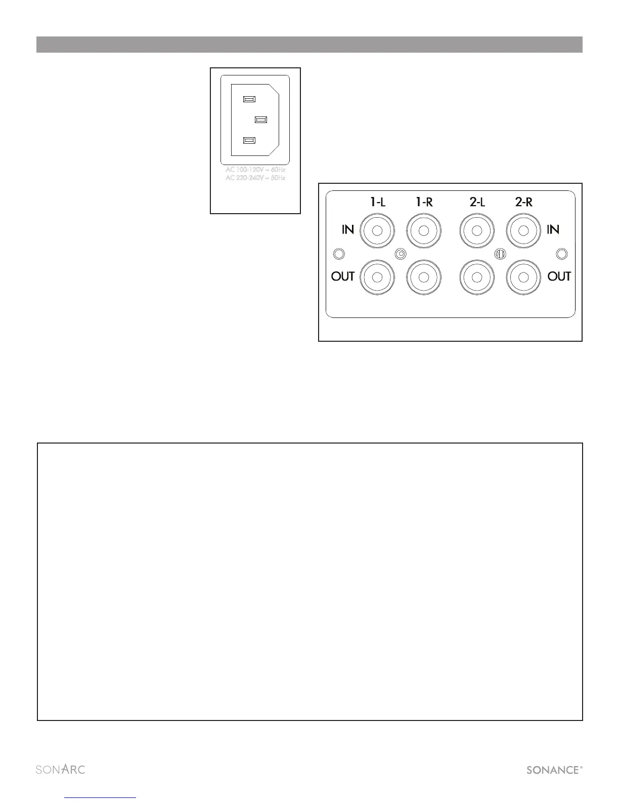
Powering the Amplifier
The Sonamp DSP 2-150 features
a removable IEC power connector
(Figure 6). A 14-gauge EIA standard
120-volt grounded power cable is
included with the amplifier.
Each time the amplifier’s power
cord is initially plugged in and the
POWER switch is turned ON, all
channel outputs are disconnected
for approximately 12 seconds and all
PROTECTION LEDs will illuminate briefly
while the amp boots up.
IMPORTANT: DO NOT PLUG THE POWER CORD INTO THE WALL
OUTLET UNTIL ALL SYSTEM CONNECTIONS HAVE BEEN MADE
AND VERIFIED.
Plug the female end of the power cable into the Power Connector
on the amplifier’s rear panel and plug the male end directly into a
grounded 15 amp or 20 amp wall outlet.
IMPORTANT: DO NOT PLUG THE AMPLIFIER’S POWER CORD
INTO A CONVENIENCE OUTLET ON ANY OTHER AUDIO OR
VIDEO COMPONENT.
If the electrical service is subject to frequent sags, spikes, or
brownouts, a power conditioner designed for use with high fidelity
equipment should be employed to protect the amplifier.
CAUTION: FOR CONTINUED PROTECTION AGAINST FIRE,
REPLACE THE FUSE WITH ONLY THE SAME TYPE AND RATING.
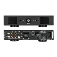
Source Connections/Selection DSP 2-150
There are two options when connecting audio inputs to the
DSP 2-150 amplifier (see Figure 8):
Primary Line Inputs 1-L, 1-R - Use these inputs for primary
audio source.
Secondary Line Inputs 2-L, 2-R - Use these inputs for a secondary
audio source, paging, or a doorbell.
Amplifiers Power Requirements: 15 AMP Breaker 20 AMP Breaker
Model Input Voltage Output Power (sinewave) Draw Watts Qty of Amplifiers Qty of Amplifiers
DSP 2-150 100-120V AC Full Power All Channels @8 ohms 371 3 5
Full Power All Channels @4 ohms 392 3 4
1/8 Power All Channels @8 ohms 72 20 26
1/8 Power All Channels @4 ohms 74 19 25
@ Idle 31
IP/IR Standby 1.5
@ Standby 0.48
13 AMP Breaker 20 AMP Breaker
Model Input Voltage Output Power (sinewave) Draw Watts Qty of Amplifiers Qty of Amplifiers
DSP 2-150 220-240V AC Full Power All Channels @8 ohms 359 4 5
Full Power All Channels @4 ohms 376 3 5
1/8 Power All Channels @8 ohms 69 20 27
1/8 Power All Channels @4 ohms 71 20 27
@ Idle 28
IP/IR Standby 1.1
@ Standby 0.5
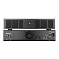
FIGURE 8: SONAMP DSP 2-150 LEFT, RIGHT LINE INPUTS
FIGURE 7: SONAMP DSP 2-150 MULTI-CHANNEL AMPLIFIER POWER REQUIREMENTS
IN
O
UT
1-L 1-R
LEVEL LEVEL
B
RIDGE
OFF ON
C
AUTION
RISK OF ELECTRIC SHOCK
D
O NOT OPEN
AVIS
RISQUE DE CHOC ELECTRIQUE
NE P
AS OUVRIR
S/N
T5AL / 250VAC
2-100
AC 100-120V ~ 60Hz
CAUTION
R
EPLACE FUSE ONLY WITH
S
AME TYPE AND RATING
ATTENTION
R
EMPLACER UNIQUEMENT AVEC LE
MEME TYP
E ET CALIBRE DU FUSIBLE
VOLTAGE TRIGGER
IN OUT
AUTO ON
OFF
1 - LEFT
1 - R
IGHT
BRIDGE
CLASS 2 WIRING
VOLTAGE
AUDIO
3-30 VOLTS
AC or DC
8 Ω MIN
AC 220-240V ~ 50Hz
52 watts
FIGURE 6: IEC POWER
CORD CONNECTION
 Loading...