4
3. Reserve the speaker module in a safe place for step 8.
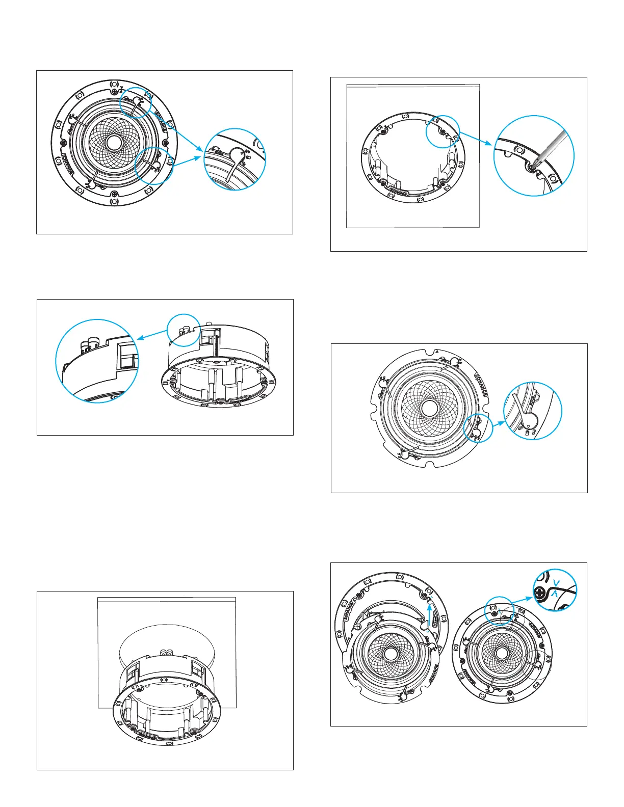
4. Secure the speaker wires to the speaker frame using
the spring loaded connector posts (see Figure 8).
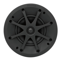
Figure 7: Remove Speaker Module from Frame
5. The speaker’s connector posts are spring-loaded.
Push the top of each connector post down to open
the connector and insert the exposed wires into the
holes in the posts.
6. The speaker’s positive post is labeled with a red dot;
the negative post is labeled with a black dot.
7. Install the wired VX speaker frame into the cutout
in the installation surface. Make sure all Roto-Lock
toggle feet are retracted so that they are tucked
within the mounting hole’s borders and then insert
the speaker frame into the hole (see Figure 9).
Figure 8: Secure Speaker Wires
8. Tighten the four screws on the front bafe to clamp
the Roto-Lock toggle feet into position, securing the
speaker frame to the surface (see Figure 10).
Figure 9: Inserting Speaker Frame
IMPORTANT: Always use low-torque settings when
using a screw gun and go very slowly; never over
tighten.
9. Use thumb pressure to rotate the VX speaker module
Flex Frame latch into the middle HOLD position (see
Figure 11).
Figure 10: Securing the Frame
11. Press rmly to snap the speaker into the frame.
Once you hear the “click,” the speaker will be secure.
Carefully remove your hand to ensure the speaker is
locked into place.
Figure 12: Aligning the Speaker Frame
2. Remove the speaker module from the frame (see
Figure 7).
Figure 11: Move Latch to Middle HOLD Position
10. Firmly and uidly snap the VX speaker module into
the installed VX speaker frame. Line up the bright
blue alignment n of the speaker module with the
matching blue alignment notch on the speaker
frame (see Figure 12).