3
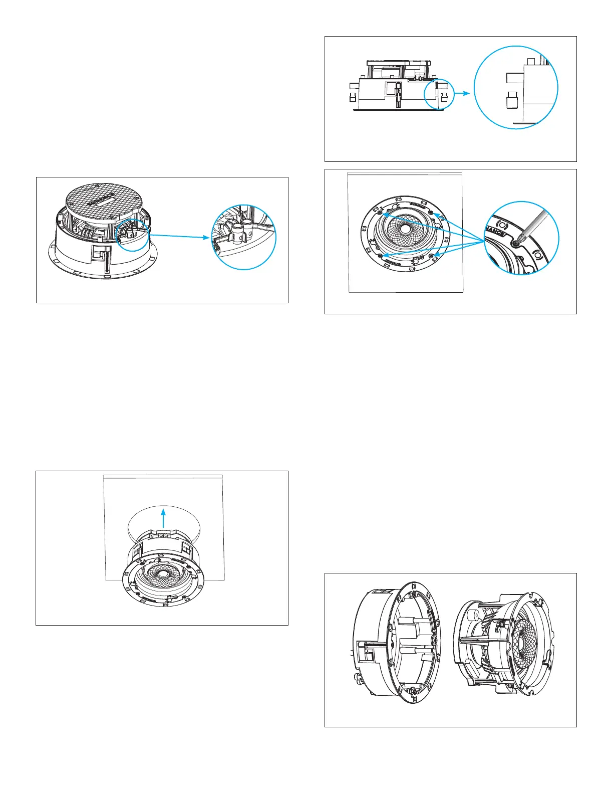
Figure 3: Roto-Lock Toggle Feet Retracted
INSTALLING INTO THICKER SURFACES
The Sonance Roto-Lock system can accommodate
material thicknesses up to 1.5” (38mm) out of the box.
For deeper substrates that are up to 2.125” (54mm) thick,
remove the tip of the Roto-Lock toggles before inserting
the speaker into the cutout opening (see Figure 4).
7. Insert the speaker into the mounting hole and
tighten the four screws on the front of the speaker
bafe (see Figure 5).
4. The speaker’s positive post is labeled with a red dot;
the negative post is labeled with a black dot.
5. After making all connections, double-check that you
connected amplier “+” to speaker “+” and amplier “–”
to speaker “–”.
Sonance Visual Experience Series Speakers feature an
exclusive integral RotoLock
®
mounting system for quick
mounting directly into existing walls and ceilings.
6. Make sure all the Roto-Lock toggle feet are retracted
so that the speaker can t within the mounting hole
(see Figure 3).
8. The Roto-Lock clamps will automatically rotate into
position and begin clamping the speaker.
Figure 5: Tightening the Roto-Lock Screws
Figure 4: Remove Roto-Lock Toggles Before Inserting
Speaker into Cutout Opening of Thick Surfaces
IMPORTANT: Always use low-torque settings when
using a screw gun and go very slowly; never over
tighten.
IMPORTANT: Adjusting the tension of the Roto-Lock
Clamps to help the speaker sit at with the surface will
help ensure proper grille contact all the way around
the speaker.
TWO-STAGE INSTALLATION
Sonance Visual Experience speaker models can be
installed leveraging a unique two-stage process which
allows the installer to separate the speaker frame from
the speaker module to easily hold, wire, and secure
the frame to the installation surface (see Figure 6). This
feature makes it simple to pre-wire with maximum
visibility and maneuverability without risk of dropping
the speaker while on a ladder.
Figure 2: Connection Terminals
2. Strip 1/4” – 1/2” (6mm – 13mm) of insulation from each
speaker lead. Twist the strands or tin the exposed
wire with solder to ensure that there are no stray
strands.
IMPORTANT: Stray strands that touch each other can
cause a short-circuit that can damage the amplier.
3. The speaker’s connector posts are spring-loaded.
Push the top of each connector post down to open
the connector and insert the exposed wires into the
holes in the posts (see Figure 2).
Figure 6: Speaker Frame and Module Diagram
1. Use thumb pressure to rotate the VX speaker module
Flex Frame latch into the UNLOCKED position.