User Manual for the Type 8370
WSM 6+ Transponder
UM-8370
Issue A Rev 1
vi
11.2.1 Standard Housing Wiring Connections ..................................................................... 32
11.2.2 External Remote Release Option Wiring Connections .............................................. 33
11.3 Specifications for Type 8370-1111 & 8370-4112 WSM 6+ ................................................... 34
Appendix A – Frequency Tables ............................................................................................ 36
A.1 HPR 400 Frequency Table .................................................................................................. 36
A.2 Sonardyne Wideband Frequency Table ............................................................................... 36
Definitions ................................................................................................................................... 38
Figures
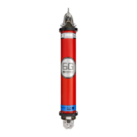
Figure 3-1 Type 8370-1111 Omni-Directional Wideband WSM 6+ ............................................. 6
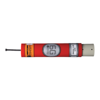
Figure 3-2 Type 8370-4112 Directional Wideband WSM 6+ ...................................................... 6
Figure 3-3 Type 8370-1111 Omni-Directional WSM 6+ Endcap ................................................. 6
Figure 3-4 Charger/Comms Connections ................................................................................. 11
Figure 4-1 WSM 6+ Pressure Relief Vent Valve ...................................................................... 13
Figure 4-2 WSM 6+ Battery Charging Connections .................................................................. 15
Figure 7-1 WSM 6+ to PC Connection Configuration ............................................................... 22
Figure 11-1 Type 8370-1111 Omni-Directional WSM 6+ Outline Drawing ................................ 31
Figure 11-2 Type 8370-4112 Directional WSM 6+ Outline Drawing ......................................... 31
Figure 11-3 5-Way Connector Pin Out and Mating Tail ............................................................ 32
Figure 11-4 8-Way Connector Pin Out and Mating Tail ............................................................ 33
Tables
Table 1-1 Related Publications .................................................................................................. 1
Table 1-2 Conventions used in this Manual ............................................................................... 1
Table 3-1 Configuration Identification Table ............................................................................... 8
Table 3-2 WSM 6+ Configuration Options .................................................................................. 9
Table 5-1 WSM 6+ Pre-Deployment Checklist ......................................................................... 19
Table 9-1 Storage Conditions .................................................................................................. 29
Table 10-1 Component Identification ....................................................................................... 30